Den ons 9 dec. 2020 kl 17:41 skrev Sven Wesley <svenne.d...@gmail.com>:
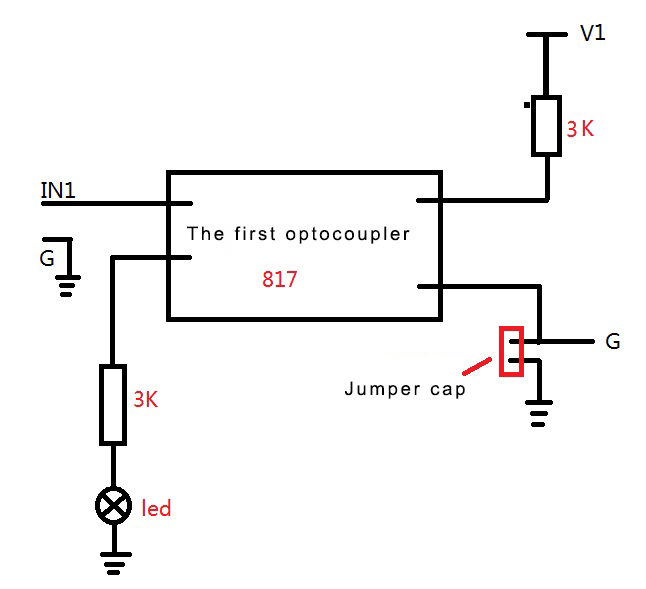
>
> Maybe my intentions have been unclear and now I'm a bit confused. The
> drives provide a high signal on one pin when they are working. If they fail
> the pin goes low. My initial thought was to connect all four pins to one
> input on the 7i96 and configure it to trigger a software stop.
> Like Gene proposed, shouldn't it work with all wires to one input with a
> diode in series on each pin?
>
> Best regards,
> Confusedius
>

Sorry if this is a double post, I believe my attachment was too big and the
post was blocked.
I just realized my own mistake. I can't wire them like I suggested. I could
probably wire all four to one input without the diodes but then I would
never see which one that actually fails (red warning LED on every drive).
All will ground if one fails and then all will fail. I mean, it would be OK
but less optimal.
Would it be possible to use optocouplers and serial to parallel adapt the
wiring? I hope my attached image makes sense but please see it as a
suggestion. I also found a sketch of the internals of the Bucck board, hope
that helps.
What do you electro ninjas think?


Bucck board design: http://www.icstation.com/images/uploads/11070_1.jpg
_______________________________________________
Emc-users mailing list
Emc-users@lists.sourceforge.net
https://lists.sourceforge.net/lists/listinfo/emc-users