Hi folks,

Replying to myself here since I've had a bit of a breakthrough but not in
the way I'd have liked. A fellow collector who also got one of these
machines at the same time opened his up and there was an extra little
bridgeboard piggybacked off some resistors next to the teletext display chip
that goes to a 7-pin socket on the rear of the case.
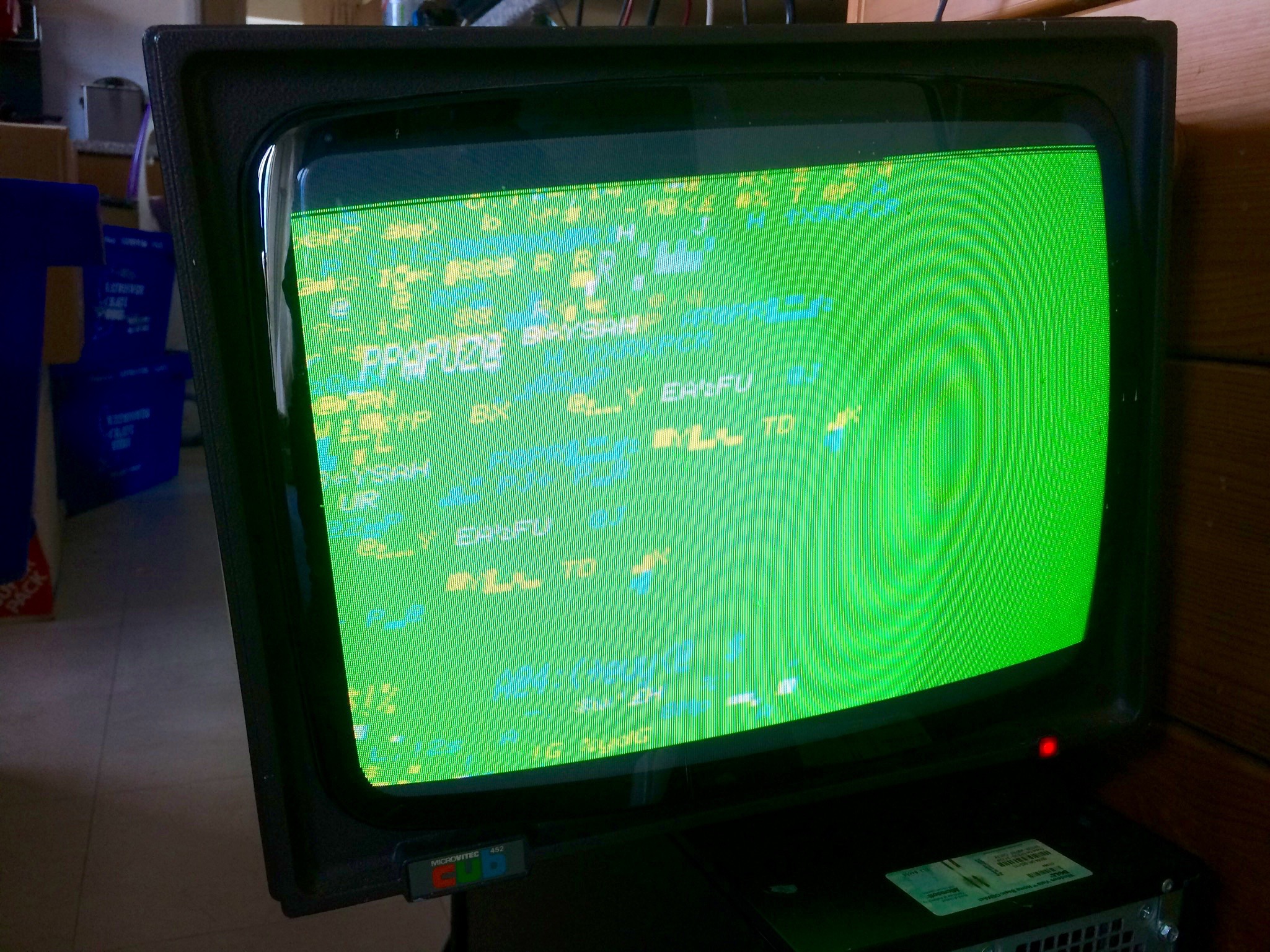
The board only has a small cap and a 74LS244 buffer chip on it so I traced
it all out and built my own to produce composite RGB + sync which I plugged
into an old Microvitec CUB monitor, the workhorse of the BBC Micro.

This is the picture I got:

http://www.binarydinosaurs.co.uk/STCExecutelScreenOutput.jpg

Funnily enough that's EXACTLY what I get on the little B&W display, the
green background explains why I thought the brightness/contrast wasn't
correct, and it's scrolling in the same way.

This means of course that the analogue board is fine and it's the INPUT to
this display chip that isn't correct, I know the chip itself is OK because I
have a Tandata TD2500 teletext terminal that uses the same device and it
works in that.

I might have to admit defeat on this one, documentation on this system is
non-existent. I've dumped the ROMs so I know they're OK and I can get the
datasheet for the 8085a CPU to check clock/address/data lines etc, RAM is
all 4116-2 so one of them could be bad as well. But there my knowledge ends.

Cheers!


On 31/10/2016 22:29, "tony duell" <a...@p850ug1.demon.co.uk> wrote:

>
>> Before I replaced the failed potentiometer (new one seen top left) the
>> display looked like its horizonal hold had gone so I reasoned that's what
>
> OK... The TDA1180 is the horizontal oscillator, etc, IC. It's well-known.
>
> Start by getting its data sheet. Indentify the horizontal oscillator
> components
> connected to pins 12, 13, 14, 15 of that IC. Typically you will find a pot
> that controls the DC voltage on pin 15 (slider of pot to pin 15 through a
> resistor). That sets the free-running horizontal frequency

That's the pot I replaced, it goes through a 22ohm resistor.

> Now try adjusting it. If you can get the oscillator to run both too fast
> and too slow (lines sloping both ways) that that part is most likely fine
> and the fault is in the sync circuit. If not, then the oscillator components
> have problems.

Yep, lines sloping both ways is exactly what happens. Perhaps bizarrely this
also seems to affect the contrast.

> Are you getting a sync pulse at pin 8 of the IC? If not, trace back from
> there to the connector to the logic board and if necessary to the video
> IC.

Pin 8 goes right back to a 74LS04 up near the RAM/ROM section of the
motherboard. I'm going to see if it's possible to assemble the whole thing
outside of the big plastic housing and still hold the screen as securely as
possible, it's a complete pain to get the screen in its swivel top and
connect up everything without risk of breakage.

> Are you getting a flyback pulse at pin 6? The horizontal control circuit is
> basically a phase-locked loop comparing the incoming sync pulses with
> flyback signal from the horizontal output stage.

Watch this space :)

--
Adrian/Witchy
Binary Dinosaurs creator/curator
Www.binarydinosaurs.co.uk - the UK's biggest private home computer
collection?

------ End of Forwarded Message