Hi folks,

Thanks for all the help so far, I've moved on quite a way but I still
haven't managed to get my head around op-amps other than the basics. If I
may trouble your experienced heads with a small circuit diagram:
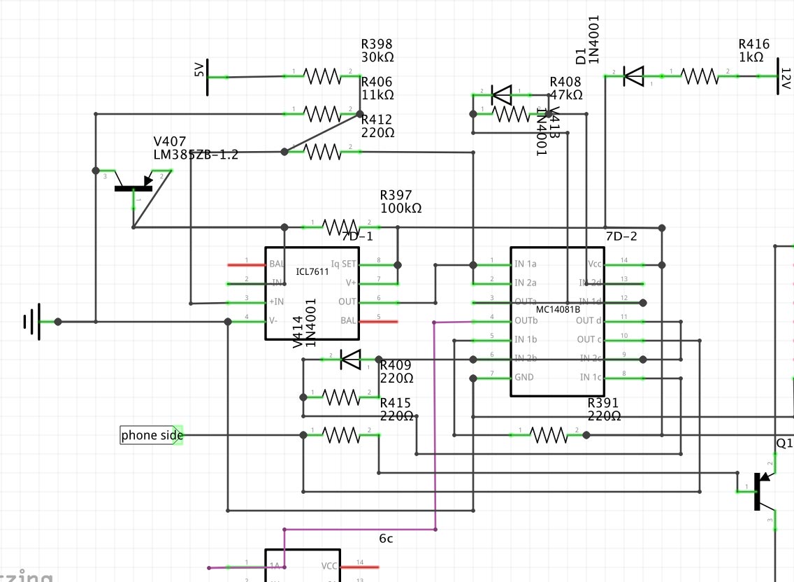
http://www.binarydinosaurs.co.uk/STCExecutelStartupCircuit.jpg

This is the full circuit of all the things I've been posting recently,
traced and drawn out as completely as I can manage. All the resistors and
diodes have been tested out of circuit and are OK and I've just realised 3
of the resistors are labelled wrongly. R409 is 47k, R415 and R391 are 100k.

IN- at the op-amp is 1.2V from the LM385ZB-1.2 which has pins 2/3 tied
together. IN+ is 1.3V. V+ is 5.3V. The purple trace is RESET for the 8085,
or should be.

Initially the LM385Z had rotted away because of battery leakage so I was
experimenting with diodes in series to try and get the IN- voltage down to
1.2V, and with two IN4148s (0.9V) the whole circuit sprang into life and I
got RESET at the 8085. For two seconds, then it would cycle for two seconds.
This maybe expected behaviour, I don't know.

3 diodes gave me 1.3V which produced nothing at the op-amp output, probably
because there was no difference between IN+ and IN-?

On a whim I managed to solder new legs onto the old LM385Z and it works,
giving 1.2V at IN-, but the output is still only 0.2V.

I don't mind admitting I'm stumped :)

--
Adrian/Witchy
Binary Dinosaurs creator/curator
Www.binarydinosaurs.co.uk - the UK's biggest private home computer
collection?