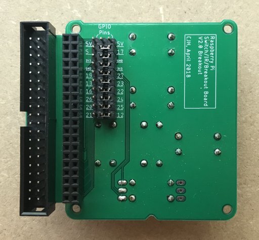
I made a second iteration. I learned the benefits of having a ground plane (or two!) for signal routing, and I improved the layout so that its easier to connect switches to GPIO pins without soldering. The middle column is the switch pins, the right hand column is some commonly unused GPIO pins, and the left column is some alternatives in case some of the pins in the right column are taken by other devices. So every switch pin has a choice of two GPIO pins that can be connected via jumpers alone, but if a different configuration is needed then jumper leads might be needed. The two alternative arrangements of legs on the IR receiver can also be accommodated by the third and fourth rows of pins.
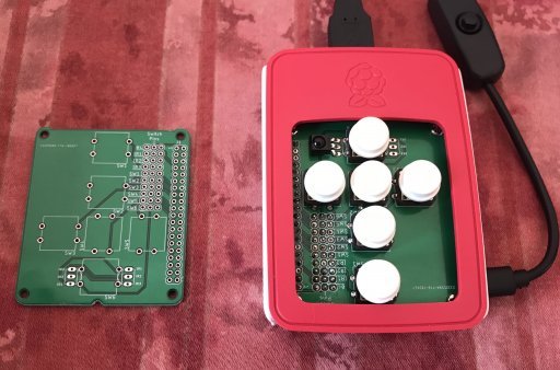
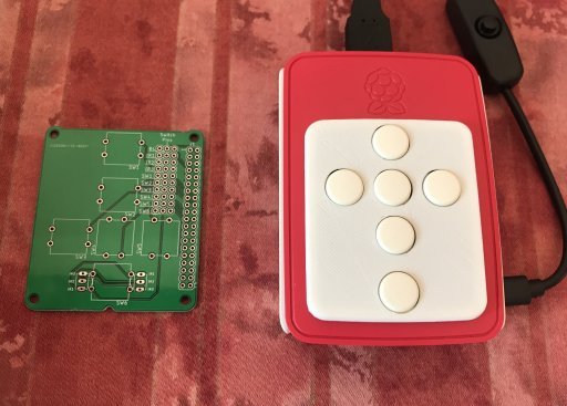
[image: http://www.cjh.me.uk/MyPhotobucket/cache/DIYHifi/RPi%20Board/V2_0%20Breakout_512.jpg] I also made a version without the breakout tab on the side so that it fits wholly inside the official case. In this case, there would be no other devices to the RPi, so any of the available GPIO pins could be used. [image: http://www.cjh.me.uk/MyPhotobucket/cache/DIYHifi/RPi%20Board/V2_0%20Internal%201_512.jpg] [image: http://www.cjh.me.uk/MyPhotobucket/cache/DIYHifi/RPi%20Board/V2_0%20Internal%202_512.jpg] ------------------------------------------------------------------------ chill's Profile: http://forums.slimdevices.com/member.php?userid=10839 View this thread: http://forums.slimdevices.com/showthread.php?t=108963
_______________________________________________
diy mailing list
diy@lists.slimdevices.com
http://lists.slimdevices.com/mailman/listinfo/diy