On 12/20/2015 11:47 AM, Gene Heskett wrote:
> On Sunday 20 December 2015 12:15:21 John Thornton wrote:
>
>> Back from shopping...
>>
>> Pencil sketch of the power side
>> http://gnipsel.com/images/bp-knee-mill/bpel03.in
> the left box probably needs the paint cleaned off under it, and maybe a
> star washer under the spade lug for extra connection bite. And there
> ought to be a similar ground to the box in the right box. But as sub
> boxes generally have isolated busses for the static (bare wires in the
> romex */3 wires) in order to bot short circuit the connection at the
> main entrance a foot or so from the meterhead.
>
>> Incoming terminal block on left panel where extra ground is
>> http://gnipsel.com/images/bp-knee-mill/bpel04.jpg
> Here I cannot see the above green wire, the static, while connected to
> the  to the box, but it does not leave to connect the rest of the stuff,
> just the white (neutral) and black (127 hot) wires leaving are all I see
> leaving. Tieing to the box, is to ground the box to the static
> grounding.
>
>> next terminal block on right panel
>> http://gnipsel.com/images/bp-knee-mill/bpel05.jpg
>>
> And here, unless its in the block mounting for the two green wires I can
> see, and I am not at all familiar with that style of terminal block,
> they are floating.  Are the two pieces of SJ I see coming in at the top,
> source or load?
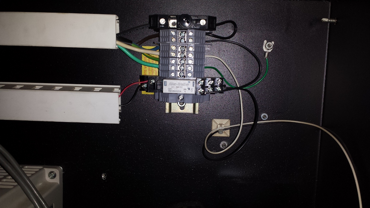
The green/yellow terminal blocks are standard ground blocks, the center
screw tightens a gripper that forces a tight metal to metal contact with
the DIN rail and the terminals. It's very much grounded to the DIN rail
and the DIN rail is fastened to the back plane with welded on studs and
star washers and nuts.

http://www.automationdirect.com/adc/Shopping/Catalog/Terminal_Blocks/DINnector_DIN-Rail_Terminal_Blocks/Ground_Terminal_Blocks/DN-G10

They are very expensive...
> Offhand, it does tend to look like a noise factory from here. :(  Those
> green wires should come from the real ground at the service entrance and
> go all the way to that single point bolt in the driver cabinet wall,
> then from there to everything else as a star ground.
>
>> JT
>>
>> On 12/20/2015 8:37 AM, Gene Heskett wrote:
>>> On Sunday 20 December 2015 08:20:38 John Thornton wrote:
>>>> I have a BP knee mill with an Anilam 1100M CNC kit on it. I've
>>>> removed all the Anilam controls a while back. I've retained the
>>>> drives and power supply and added a GS2 VFD for the spindle. I have
>>>> a 5i25 7i77 setup. From the get go I've had problems with the
>>>> electronics on this machine. The VFD is controlled by modbus via
>>>> the gs2 component. The VFD gets reset to default parameters all the
>>>> time from noise on the modbus. the 5i25 get sserial errors. The
>>>> sserial errors are so bad now it won't even move an axis. The
>>>> spindle works ok. The power supply is a simple bridge rectifier
>>>> with a huge blue cap and a large power resistor across the cap.
>>>>
>>>> Peter keeps telling me it's a grounding issue so where do I start
>>>> looking and what do I need to do?
>>>>
>>>> Thanks
>>>> JT
>>> Start with a roll of flat braid equ to a 8 or 10 gauge wire.
>>> Establish a bolt to the case of the controller as a master ground,
>>> and make sure everything that references ground in the controller
>>> box is grounded at this bolt.
>>>
>>> Tie this bolt to the buildings static ground using that pin of the
>>> controllers power cable, BUT not to the building supply neutral as
>>> thats usually noisy as can be.  Or to a real ground rod but that may
>>> have a considerable damaging joltage on it when there is lightning
>>> nearby so is both against the NEC and would be poor practice.
>>>
>>> Then extend that ground, using this braid, to the bridgeports main
>>> casting, and perhaps also to the table and knee as the lube oil in
>>> the ways might preclude a really good ground on the table without
>>> it.
>>>
>>> Extend that ground from that bolt to the computers case if it is
>>> separated from the controller box.
>>>
>>> This is called a star ground system, where everything is common at
>>> this bolt.  If you can disconnect each wire from that bolt, and
>>> still measure continuity of 200 ohms or less from the bolt to the
>>> disconnected wire, then that wire has an unwanted ground somewhere,
>>> run it down and remove it, you want that to be "grounded" only at
>>> that bolt.
>>>
>>> The idea is that even if it does bounce a bit from a nearby
>>> lightning strike, it all bounces in unison with no big voltage drops
>>> between anything that can damage it, or induce noise that would be
>>> miss-detected as a signal.
>>>
>>> Years ago when I was screwing with vz & their bad copper, I figured
>>> on losing a modem everytime I heard thunder. Getting PO'd, I first
>>> opened up the wall a bit, pulled out the duplex that was going to
>>> power what I had in mind, and soldered all the connections in that
>>> box. Then I bought the biggest surge arrestor I could find, one that
>>> had phone line & cable tv arrestors in it.  And I bought the biggest
>>> home UPS I could find. Everything in this room but the lights is
>>> plugged in either to that UPS or that surge arrestor, and both are
>>> plugged into this all soldered duplex. Now lightning can hit the
>>> pole my transformer is on, possibly bouncing everything in this room
>>> by 100 kilovolts, but it all bounces in unison and I haven't lost a
>>> modem or anything else that I could associate the loss with local
>>> lightning strikes. But since I did get, from a wired keyboard I was
>>> typing on at the time, a really good jolt thru my fingers like
>>> shuffling ones feet on the rug and then grabbing the doorknob, but
>>> it didn't hurt the computer or the keyboard, but I now use wireless
>>> keyboard and mice.
>>>
>>> If the frame of the bridgeport is grounded thru other means, such as
>>> a 3rd pin on a power cable, this should be defeated in order to
>>> remove the potential ground loop which can be a source of quite a
>>> bit of induced noise.
>>>
>>> Motor drive, and feedback cables from the motors should be shielded,
>>> with the shields cut off at the motor ends of the cable but tied to
>>> this bolt at the controller end, thereby interrupting that potential
>>> ground loop.
>>>
>>> The general idea is to have one common "ground" point, even if its
>>> is not an earthen ground. That s/b, by the NEC, at the service
>>> entrance, a minimum of two full rods driven 6 feet apart, with an 8
>>> gauge wire bonding them to the buildings static ground for the 3rd
>>> pin of all the duplexes and neutral from the pole drop, the only
>>> place it is legal to interconnect them.  Hanging an amprobe on any
>>> of the bare static wires in the service box should get you a zero
>>> reading regardless of what is powered up.  If you do see a reading,
>>> something out on that circuit is miss-wired. Fix it. Its just good
>>> practice.
>>>
>>> It and I, may sound arbitrary John, but it works.  And its NEC
>>> legal. If you have a decent scope, just waving a probe around with
>>> the gain turned up near suspected noise sources can be very
>>> educational.
>>>
>>> I've had to follow too many electricians around, fixing their
>>> mix-n-match attitude about static and neutral being the same thing,
>>> way too many times.
>>>
>>> Let us know what you did find when you've cleaned up the problem,
>>> please.
>>>
>>> Cheers, Gene Heskett
>> ----------------------------------------------------------------------
>> -------- _______________________________________________
>> Emc-users mailing list
>> [email protected]
>> https://lists.sourceforge.net/lists/listinfo/emc-users
>
> Cheers, Gene Heskett


------------------------------------------------------------------------------
_______________________________________________
Emc-users mailing list
[email protected]
https://lists.sourceforge.net/lists/listinfo/emc-users