Andy,
Here's a more complete PDF that shows the spindle cover plate in relation to
the new spindle motor and the large hole where the original motor used to be.
http://www.autoartisans.com/mill/SpindleMountAssembly.pdf
The spindle cover plate has holes for the eventual power draw bar.
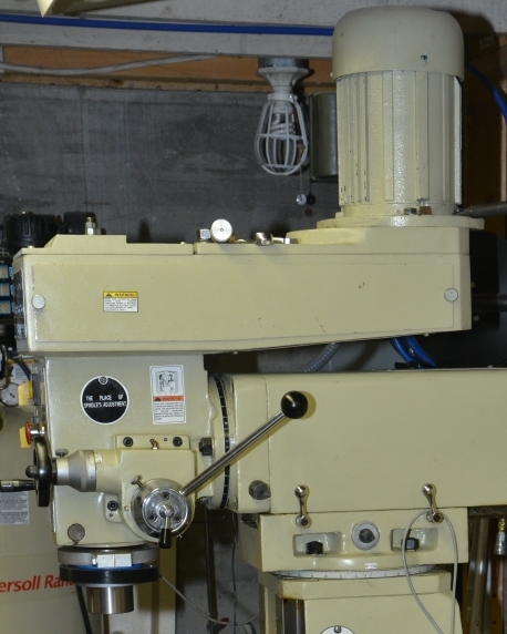
and to put it into perspective, here's a photo of the original drive
configuration with the huge 2HP single phase motor.   You can see that the
motor is raised even more and that cast iron plate is deep enough to provide
enough thread for tightening down the motor after tensioning the belts.
http://www.autoartisans.com/mill/MillDriveSection.jpg

The top rectangular section that houses the pulleys and belts is actually a
separate casting bolted and cleaned up with filler to make it look like one
piece.

There is no reason that I can't make a much shorter weldment that that holds
just the two pulleys, spindle motor and power draw bar.   The shorter Bergerda
spindle motor means I now have headroom to build a spacer raising block between
the column and the head to give me a bit more space over the rotary table and
even a mount for a horizontal spindle drive.

But first things first.  LinuxCNC powered spindle.  Draw bar and tool changer
and then raising block.  Then maybe think about updating  how the motor and
power draw bar are mounted.  I don't know what I want yet so it's pretty hard
to design.

John

> Not really. You could consider moving the adjuster plate to the other side
> of the main plate to have less overhang on the motor shaft.
> That would need a bigger hole in the main plate, making it weaker. But the
> reduced moment load from the belt tension might make that an overall win.
>


_______________________________________________
Emc-users mailing list
[email protected]
https://lists.sourceforge.net/lists/listinfo/emc-users