                            EV Digest 4328

Topics covered in this issue include:
  1) Re: possible DCP controller issue - help
        by Mark Farver <[EMAIL PROTECTED]>
  2) Re: Todd DC/DC converter noise?
        by "Joe Smalley" <[EMAIL PROTECTED]>
  3) Re: Resting voltage vs state-of-charge
        by James Massey <[EMAIL PROTECTED]>
  4) Re: Contactor controller, Was:RE: Mechanical PWM Controllers
        by Justin Southam <[EMAIL PROTECTED]>
  5) Re: Contactor controller, Was:RE: Mechanical PWM Controllers
        by Justin Southam <[EMAIL PROTECTED]>
  6) RE: Progress on my Hybrid Trike
        by "Stu and Jan" <[EMAIL PROTECTED]>
  7) installing batteries
        by "ohnojoe" <[EMAIL PROTECTED]>
  8) Re: BB600 battery pickup
        by Seth Allen <[EMAIL PROTECTED]>
  9) Re: installing batteries
        by "Roland Wiench" <[EMAIL PROTECTED]>
 10) Re: 4 prong connector
        by "Lawrence Rhodes" <[EMAIL PROTECTED]>
 11) RE: concept question
        by [EMAIL PROTECTED]
 12) Re: installing batteries
        by Evan Tuer <[EMAIL PROTECTED]>
 13) TdS Report #20: Tour de Sol Events Open to the Public
        by [EMAIL PROTECTED]
 14) RE: Sim Math
        by "Philip Marino" <[EMAIL PROTECTED]>
 15) Re: Transfer case as transmission
        by Eric Poulsen <[EMAIL PROTECTED]>
 16) RE: Sim Math
        by David Dymaxion <[EMAIL PROTECTED]>
 17) RE: Sim Math
        by David Dymaxion <[EMAIL PROTECTED]>
 18) Re: BB600 battery pickup
        by Fortunat Mueller <[EMAIL PROTECTED]>
 19) Re: Sim Math
        by David Dymaxion <[EMAIL PROTECTED]>
 20) Re: electric heater core questions
        by Victor Tikhonov <[EMAIL PROTECTED]>
 21) Water heater (Re: electric heater core questions)
        by Victor Tikhonov <[EMAIL PROTECTED]>
 22) Re: Got my taperlock hub off!
        by David Dymaxion <[EMAIL PROTECTED]>
--- Begin Message ---
Steven Ciciora wrote:
I'm having a similar problem.  As a matter of fact, I
got the truck at a great price because of this
problem.  Both the previous owner and myself thought
it was a slipping clutch.  Between the both of us, we
replaced just about everything possible associated
with the cluth; no improvement.  Some notes on my
problem:
-Only happens when moving.  At a stop, with break
pressed (stalled motor), does not happen.  I take this
to mean that it requires the motor to be under load,
or the controller to be delivering power, not just
current.  The stalled motor (no back emf, but lots of
current) isn't delivering much power.
-Seems to (usually) go away when it warms up.   But
for all practical purposes, it is rendering the truck
unusable.
Check the connection between the control board and the power stage. It
is 6pin header connection and when it gets corroded or loose you will
have power fluctuations.
In my case one of the springs on the female (control board) side of the
connector had cracked. The connector is tin plated, and seems to
corrode pretty badly in an EV environment. A gold plated version costs
only slighty more, you might want to have both halves of the connection
replaced by someone with some soldering skill. My roommate has at least
one more connector and would probably do the work for 6pp... (6 pack
and a pizza)
Mark Farver
--- End Message ---
--- Begin Message ---
At very light loads the control chip skips cycles.
This produces an audible hiss.
All of mine make that noise at light loads.

Joe Smalley
Rural Kitsap County WA
Fiesta 48 volts
NEDRA 48 volt street conversion record holder
[EMAIL PROTECTED]


----- Original Message -----
From: "Nick Viera" <[EMAIL PROTECTED]>
To: "EVDL" <[email protected]>
Cc: "AustinEV_list" <[EMAIL PROTECTED]>
Sent: Sunday, May 01, 2005 3:50 PM
Subject: Todd DC/DC converter noise?


> Hi,
>
> I'm curious to know if it is normal for the Todd DC/DC converters to
> make a (pretty noticeable) buzzing/hissing type sound while in
> operation? The noise I'm hearing is loudest when the DC/DC is barely
> loaded, and almost non-existent when the DC/DC is heavily loaded (i.e.
> the intensity of the sound is inversely proportional to the electrical
> load on the DC/DC's outputs).
>
> My first guess is that the Todd converter uses a lower switching
> frequency than my DCP unit does, and that I'm simply hearing the unit
> switching (and varying duty cycle as the load changes)?
>
> Or is something else going on hear :-)
>
> Thanks,
> --
> -Nick
> http://Go.DriveEV.com/
> 1988 Jeep Cherokee 4x4 EV
> ---------------------------
>
--- End Message ---
--- Begin Message ---
At 09:45 PM 1/05/05 -0700, Joe Smalley wrote:
The referenced numbers are about right for flooded batteries.
The temperature compensation is about right as well.
A full and healthy Hawker, Optima or Orbital will be about 13.1 volts and a
discharged one will be about 12.1 volts making them about 0.3 volts higher
than listed in the referenced chart. As they age, the resting voltage drops.
Also Dean Thompson wrote:
> Hi James,
>
> You might find this link useful, I did!
> http://www.uuhome.de/william.darden/
>
> Is this what you're looking for:
> http://www.uuhome.de/william.darden/carfaq4.htm#vrla_soc
Thanks, guys. Exactly as required, and then some!
James
--- End Message ---
--- Begin Message ---
Hi Jerry, thanks for all the info. Will save and study it.

Saw your comment of using CC for a budget version of the Freedom EV. Thats
where i'm coming from. For $50-100 extra the simple CC can be made a little
smarter and driver friendly.

Justin


--
No virus found in this outgoing message.
Checked by AVG Anti-Virus.
Version: 7.0.308 / Virus Database: 266.11.0 - Release Date: 29-04-05
--- End Message ---
--- Begin Message ---
Hi Lee, thanks for all the input.

The current and rpm monitors can be used to prompt the driver the change
down when rpm gets low and current rises hopefully avoiding having to drop
another voltage step to limit current. Actually a feature like this could
be useful on other controllers to help unfamiliar drivers come to grips
with the subtleties of EV driving.

Thanks for the rectactor circuit. Much better than mine. Do S4a and b need
to be ganged? The diodes should prevent any excitement. It appears by
alternating them with S3 enabled you could have a 3/4 step and maintain
approximate battery SOC balance.

As i mentioned in my reply to Jerry, my idea is to make a CC friendly
enough not to have to give an unfamiliar driver a list of do's and don'ts,
to have it protect the motor, batteries and itself the way a PWM controller
can.

Justin

At 11:19 28-04-05 -0700, Lee wrote:
>Justin Southam wrote:
>> I recall from PWM controller threads that current limiting is often
>> not controlled by software because of risk of glitch or delay.
>
>Correct. It is generally considered a cheap or bad design to depend on
>the micro for this, as a simple program bug or noise glitch would
>destroy the controller.
>
>> A contactor controller is obviously much less sensitive to over
>> current than a PWM controller but I'd rather the current limit
>> activates then notifies the PIC. Same with the rev limiter.
>
>Except that in a contactor controller, you can PREDICT whether
>increasing the voltage will cause the current to go too high. The micro
>has plenty of time to think about it, double-check its results, and THEN
>allow the voltage to be stepped up.
>
>For example, you want a 500 amp current limit. You are at the 36v step
>and the motor is drawing 300 amps. Doubling the voltage to 72v will also
>cause the current to double, to 600 amps. Thus, don't switch! Wait until
>the motor speed increases so the current falls to 250 amps. Then you can
>safely switch to 72v and the current will double to 500 amps.
>
>Now, this direct relationship between motor voltage and current isn't
>exact; any real motor will vary from this slightly. It works best at low
>currents; at high currents, the motor current will more than double when
>you double the voltage.
>
>Same with rpm. The motor has a precise relationship between voltage,
>current, rpm, and torque. If you measure voltage and current, you can
>calculate rpm and torque (or get it from a lookup table or graph). So if
>you have a current sensor, you don't need an rpm sensor. Or if you sense
>rpm, you don't need to sense current.
>
>My point was that you may want to sense both anyway, just for redundancy
>and fault analysis. If one sensor malfunctions, you can tell something
>went wrong.
>
>> I hadn't considered contact life. 2 thoughts spring to mind. The
>> contactors would close under load but the idea is the main contactor
>> would be open when these contactors open, I assumed most wear
>> (arcing) would occur on opening.
>
>Generally true, especially with inductive loads like a motor.
>
>But, if you always use your main contactor to break the circuit, then
>you wear it out especially fast. It's more normal to design a contactor
>controller so the load is broken by multiple contactors, both to reduce
>the stress on each one, and to equalize their life expectancy.
>
>> Or replace them with SCRs, they would turn off with the main
>> contactor.
>
>The SCRs will require heatsinking and control logic. You don't have to
>go very far down this path before you are better off just using them to
>both make and break power, and so are well on your way toward having a
>PWM controller.
>
>> Do you think a 144volt (36/72/144) 3 step system would be practical?
>> I think the 72 to 144v step is just too wide.
>
>The steps in a contactor controller are almost always 2:1. As I said,
>this causes a roughly 2:1 change in torque. If you're cruising at a
>particular speed and double the torque, the rate of accelleration is
>very small.
>
>>>> Oil filled main contactor...
>>> Why oil-filled?
>> I thought this contactor would be repeatedly and often opening
>> under load and this would minimise contact damage (arcing).
>
>It can help if it's designed for it. But such contactors are pretty rare
>in EVs. They are more likely to be found in huge power plants.
>
>With a reasonable "snubber" network, a "dry" contact will be just fine.
>Even without a snubber, it will last a long time!
>
>>> There shouldn't be any diodes in the circuit at full voltage
>>> -- just contacts and batteries.
>
>> I drew a circuit with 4 batteries with positives to anodes of
>> 4 diodes, cathodes commoned to main contactor. Battery negatives
>> to cathodes of 4 diodes, anodes commoned for negative motor
>> connection. Contactors from bat1+ to bat 2-, from 2+ to 3-,
>> 3+ to 4-. Battery 1 negative and battery 4 positive can be
>> connected without diodes but this would upset current sharing.
>
>No; the rectactor is a better circuit. Here it is (view with a fixed
>width font like Courier New or Fixedsys):
>          _________________________________||__________||___
>         |          _|_       __|__+   |   ||   |  |   ||   |
>         |       D1 /_\  S4a   ___ B1  |   S1   |  |   S2   |
>        _|_          |____||____|  -   |        |  |_      _|
>     D5 /_\       +__|__  ||   _|_     |___|/___|    \/\/\/ |
>         |       B2 ___        /_\ D2     +|\-         | R1 |_
>         |        -  |__________|          C1         _|_    _| MOTOR
>         |      S3         |                       S5 ___    _| FIELD
>         |______||_________|                           |     _|
>         |      ||         |                           |    |
>     ____|_____            |                           |____|
>   _|_       __|__+       _|_                               |
>D3 /_\  S4b   ___ B3      /_\ D6                           _|_
>    |____||____|  -        |                      MOTOR   /   \
> +__|__  ||   _|_          |                    ARMATURE |     |
>B4 ___        /_\ D4       |                              \___/
>    |__________|___________|________________________________|
>
>B1-B4 are your four 12v batteries. S1 is your main contactor, and has
>capacitor C1 across it as a snubber. R1 is your starting resistor, and
>S2 is the bypass contactor for it.
>
>S4 is your 12v/24v series/parallel contactor. When open, B3 and B4 are
>in parallel via diodes D3 and D4; and B1 and B2 are in parallel via
>diodes D1 and D2. When you close S4, it connects B1 and B2 in series,
>and B3 and B4 in series.
>
>S3 is your 24v/48v series/parallel contactor. It works with diodes D5
>and D6 to select 24v or 48v.
>
>S5 is a field weaking contactor. It wires part of the starting resistor
>across the field to get a speed halfway between two voltage steps.
>
>Notice that at full voltage (48v), there are no diodes in the power
>path. At 24v, there is only one diode in the power path (D5 and D6 are
>effectively in parallel, each carrying 1/2 the motor current). At 12v,
>there is two diode drops in the power path (D1, D2, D3, and D4 are
>effectively in parallel, each carrying 1/4th the motor current).
>
>Also note that no contactor ever needs to switch the full 48v. In an
>emergency shutdown, opening all contactors doesn't have more than 12v
>across any of them.
>--
>"Never doubt that the work of a small group of thoughtful, committed
>citizens can change the world. Indeed, it's the only thing that ever
>has!" -- Margaret Mead
>--
>Lee A. Hart  814 8th Ave N  Sartell MN 56377  leeahart_at_earthlink.net
>
>


--
No virus found in this outgoing message.
Checked by AVG Anti-Virus.
Version: 7.0.308 / Virus Database: 266.11.0 - Release Date: 29-04-05
--- End Message ---
--- Begin Message ---
Joe,

Good questions.

A single bearing lean steer requires a castor angle for the head angle.
The problem with this lean steer system is that you get the same angle at
all speeds.

I am building a 2 bearing lean and independent steer system.  I have never
seen it done before.  The steering will be done by feet only.  The
throttles, brakes, and leaning will be controlled by semi vertical bars
connected to the rear part.  I plan to hold myself at any angle by pressure
between the 2 bars.  The horizontal bearing would allow me to go straight
and lean as well (not used).

I have a video of a powered leaning trike that a test rider flipped.  As he
was leaning and steering in a left turn, the back part rotated and it
flipped over to the right.  I believe that if he had control of the back by
something like my vertical bars idea, he would not have crashed.  If you
like, I can send the video to you.

As for wheels and lateral loads, see my recumbent trike file also at
www.stulieberman.com ($100 elevator is there as well).

Trikes that use 20" or smaller diameter bicycle wheels are never bothered by
lateral force damage.  Most commercial tadpole trikes use 20" spoked wheels
and they go downhill as fast as 60 mph. However, look out when using spoked
26" or 27" wheels as they can cause a 'side' trip.

Thanks for looking and for commenting.

BoyntonStu

-----Original Message-----
From: [EMAIL PROTECTED] [mailto:[EMAIL PROTECTED] On
Behalf Of Joe Smalley
Sent: Monday, May 02, 2005 12:37 AM
To: [email protected]
Subject: Re: Progress on my Hybrid Trike

I thought the leaning bearing axis needed to be aligned with the tire patch
of the front tire.

It looks like it is parallel to the ground.

Are you sure this is right?

Where is that website and video of the tilting trike to show how they did
it?

Are the rear wheels rated to take the lateral force of a trike? It looks
like they were designed for a tilting two wheeler. Three wheelers need
stronger wheels than two wheelers because of the increased side load in
three wheeler applications.

Joe Smalley
Rural Kitsap County WA
Fiesta 48 volts
NEDRA 48 volt street conversion record holder
[EMAIL PROTECTED]


----- Original Message -----
From: "Stu and Jan" <[EMAIL PROTECTED]>
To: "EV LIST" <[email protected]>
Sent: Sunday, May 01, 2005 4:32 PM
Subject: Progress on my Hybrid Trike


> Visit www.stulieberman.com <http://www.stulieberman.com/>   and view
hybrid
> trike folder.
>
>
>
> Some details:
>
>
>
> 6-33 AH wheelchair batteries
>
> 6.5 HP B&S I/C engine powers left rear
>
> 8" 36V 80 Amp motor to be run at 48 V
>
> 12.5" wheels and frames from 2 scooters
>
> Battery case and engine/motor mount from bed frames angle
>
> Oxy/acet and oxy/propane brazing
>
>
>
> Notice 2 headsets and 2 forks:  horizontal headset/fork  #1 for leaning in
> turns, #2 fork
>
> For steering.
>
>
>
> Curtis 36-48 1204 Controller
>
>
>
>
>
> Boyntonstu
>
>
--- End Message ---
--- Begin Message ---
When I was putting in new traction batteries, the lugs began to spark as I
connected the string to the next battery.  I stopped the install.  Is this
normal?  I could imagine that the string has x number of volts while the
next battery only has 12 volts but I didn't think that there should be a
spark cause there isn't a completed circuit.

Thanks,

Joe
--- End Message ---
--- Begin Message ---
Rod was asking about the comissioning charge for BB-600s. I am not
quite sure what this chart is. And the comissioning charge is the
charge you use to bring them up from 0V, so it is quite different from
a normal charge profile.
Seth
On May 2, 2005, at 12:28 AM, [EMAIL PROTECTED] wrote:
From the 7658.pdf (TM 11-6140-203-14-4&P) page 5-3 in table 5-1 I
hope the
formating comes out right.
Table 5-1. Constant Voltage charging Rate.
Ambient Temp    2-hour Charge   4-hour          8-hour
Degrees         Constant Voltage Constant Voltage Constant Voltage
F    C          Per             Per             Per
                Cell BB-693 A/U Cell BB-693 A/U Cell    BB-693 A/U
-40 -40         1.68    32.0    1.68    32.0    1.68    32.0
-20 -30         1.68    32.0    1.63    31.0    1.58    .0.0
  0 -18         1.68    32.0    1.63    31.0    1.53    29.0
 32   0         1.63    32.0    1.58    30.0    1.53    29.0
 50  10         1.63    32.0    1.53    29.0    1.53    29.0
 80  27         1.58    32.0    1.53    29.0    1.47    28.0
100  38         1.53    32.0    1.47    28.0    1.47    28.0
120  49         1.47    32.0    1.42    27.0    1.42    27.0
I have. I did 9A. I think I extrapolated that from some literature I
had. I stopped at ~1.65VPC? They took nearly double their capacity
50Ah
for a 30Ah at 1C rated. They warmed to over 100F, maybe 110F?
I also did a test of my GE (not SAFT) BB600 batteries. Otmar hosts the
.xls file. Or e-mail me offlist if you want it.
Seth
--- End Message ---
--- Begin Message ---
If your battery frame or enclosure is a non-insulated metal, you could have a
conductance path from the batteries to the frame.  No matter how much you clean
with all the battery cleaners, you can still read a leakage voltage across the
top of the batteries.

Also, when connecting a large string of batteries in series, make sure the last
two batteries, the NEG and POS power feeds are at the far end of the strings.
It is best to keep the maximum voltage difference between each roll at about 72
volts.

I had aluminum battery boxes which always leak to the cases and could see
arcing jumping across from some batteries to the case while charging in the
dark.

I had to install plastic dividers between the batteries and between the
batteries and the battery box.  Latter, I made new battery boxes out of
fiberglass which was epoxy enamel coated with the same type of coating that is
put on sinks which is acid proof.

I do not get any arcing at all now.

Roland


  ----- Original Message -----
  From: ohnojoe<mailto:[EMAIL PROTECTED]>
  To: [email protected]<mailto:[email protected]>
  Sent: Monday, May 02, 2005 5:48 AM
  Subject: installing batteries


  When I was putting in new traction batteries, the lugs began to spark as I
  connected the string to the next battery.  I stopped the install.  Is this
  normal?  I could imagine that the string has x number of volts while the
  next battery only has 12 volts but I didn't think that there should be a
  spark cause there isn't a completed circuit.

  Thanks,

  Joe
--- End Message ---
--- Begin Message ---
Well I'd rather keep it stock. Maybe a 125v battery warmer on board (Cheap
light charger) but even the Lester when charging the pack from 0% SOC takes
13 hours. Then there's the 12v side. A DC to DC for that. It gets
expensive. The truck runs well as is. I've never heard of anyone getting
shocked by an Electravan. LR...........
----- Original Message -----
From: "Mike Chancey" <[EMAIL PROTECTED]>
To: <[email protected]>
Sent: Sunday, May 01, 2005 7:04 PM
Subject: Re: 4 prong connector
Lawrence wrote:
You have a point but if you pull out that cord while the charger is
running it will still run. Very dangerous.
Something is strange, because my Lester off-board charger with my Jet shut
down as soon as you unplugged it from the EV. This is getting
complicated. Both solutions are hazardous.
This thing has a cover maybe the thing to do is use a standard 4 prong
twist (or 5) drill out the center for the safety switch circuit. Then put
a lock on the cover. The car won't run with that circuit open. That
might be better. However the worst that could happen is a burn. Unless
you get a finger from each hand on it. Ewww. Bad thought. Yes Lock the
cover. LR............
Since it is truck and the additional weight probably isn't all that much a
factor, why not just mount the charger in the bed and switch to a three
prong male inlet and cord feeding AC into the truck? That would also open
things up to allow opportunity charging. An insane picture of equipping
your truck with an Avcon inlet comes to mind. A Lester boat anchor
powered from an Avcon? :P Of course switching to a more modern, light
weight, efficient and flexible on-board charger that could run on both 120
and 240 would be the best answer. Is the EV worth the investment?
Thanks,
Mike Chancey,
'88 Civic EV
'95 Solectria Force
Kansas City, Missouri
EV List Photo Album at: http://evalbum.com
My Electric Car at: http://www.geocities.com/electric_honda
Mid-America EAA chapter at: http://maeaa.org
Join the EV List at: http://www.madkatz.com/ev/evlist.html
Wasting imported oil is not an act of patriotism, conserving it is.
--- End Message ---
--- Begin Message ---
Sorry for the delayed response.
Probably a VW Rabbit or Cabriolet.

-----Original Message-----
From: Ryan Stotts [mailto:[EMAIL PROTECTED]
Sent: Saturday, April 30, 2005 8:42 PM
To: [email protected]
Subject: Re: concept question


Jeff and Diane wrote:

> Back to the ADC or Warp motors.

Maybe I missed it, but what kind of vehicle are you going to be converting?
--- End Message ---
--- Begin Message ---
Is your DC-DC converter "always on"?  If so, that's what's causing it.
Check that all the loads are really disconnected, as you don't really
want to have sparks!

--

EVan
http://www.tuer.co.uk/evs2


On 5/2/05, ohnojoe <[EMAIL PROTECTED]> wrote:
> When I was putting in new traction batteries, the lugs began to spark as I
> connected the string to the next battery.  I stopped the install.  Is this
> normal?  I could imagine that the string has x number of volts while the
> next battery only has 12 volts but I didn't think that there should be a
> spark cause there isn't a completed circuit.
>
> Thanks,
>
> Joe
>
>
--- End Message ---
--- Begin Message ---
TdS Report #20: Tour de Sol Events Open to the Public

There are two places where the Tour de Sol vehicles and teams will be on
display for the public.

The first is at the Saratoga Spa State Park at the Auto Museum in Saragota
Springs, New York.  The Tour will be part of the annual Saratoga Automobile
Museum Auto Show on Saturday, May 14, 2005, from 10 am to 5 pm.  May 15th is
the rain date.  Details are at
        http://www.saratogaautomuseum.com/springautoshow.html

The Auto Show features hundreds of antique, classic, and show piece vehicles,
along with a series of 20 minute workshops.  Three talks associated with the
Tour are:

        10:30 am
        "Design and Construct a Prototype Hybrid"
        Mike Seal
        Vehicle Research Center of Western Washington University

        12:30 pm
        "Hydrogen Fuel Cell Vehicles"
        James Dunn
        Center for Technology Commercialization

        1:30 pm
        "Owning and Servicing a Hybrid"
        Craig Van Batenburg
        Automotive Career Development Center


The second public event is on Monday, May 16, 2005, at the Empire State Plaza
in Albany, New York, from 10 am until 2 pm.  The Award Ceremony will be at 11
am.

Along with the Tour de Sol participants on display, New York State Clean Cities
and Clean Fueled Vehicle Programs will have displays featuring the member
businesses and partners.  The New York State Energy Research and Development
Authority (NYSERDA) is sponsoring that event.

Make plans to visit the Tour de Sol this year!

 -      -       -       -
 The complete set of Tour de Sol Reports for 2005 can be found at:
             http://www.AutoAuditorium.com/TdS_Reports_2005
 The complete set of past Tour de Sol Reports can be found at:
             http://www.FovealSystems.com/Tour_de_Sol_Reports.html
 -      -       -       -
 The above is Copyright 2005 by Michael H. Bianchi.
 Permission to copy is granted provided the entire article is presented
 without modification and this notice remains attached.
 For other arrangements, contact me at  +1-973-822-2085 .
 -      -       -       -
 For more on the NESEA Tour de Sol, see the web page at
                        http://www.TourdeSol.org
 -      -       -       -
 Official NESEA Tour de Sol information is available from the sponsor,
 the Northeast Sustainable Energy Association (NESEA) at
  413 774-6051 , and  50 Miles Street, Greenfield, MA 01301 , and
  [EMAIL PROTECTED] .  All media enquiries should be addressed to ...

        Jack Groh
        Tour de Sol Communications Director
        P.O. Box 6044
        Warwick, RI  02887-6044

        401 732-1551
        401 732-0547 fax
        [EMAIL PROTECTED]
--- End Message ---
--- Begin Message ---
I haven't looked this over in detail, but, at first glance, it seems that
you are equating acceleration and force in a couple of places:
First, in your initial equation:
acceleration = acceleration from motor � rolling drag � aero drag
"rolling drag" sounds like a force ( as does "aero drag"), not an
acceleration
and, later, here:
dv/dt = min(a_traction, P/(m*v�)) � ug � a2 * v^2 / m
In this equation, ug is a force, not an acceleration - you need to divide it
by m ( like you did for the air drag term)
Also ( and maybe I just missed this) you need the motor characteristics in
here somewhere (current draw and torque as a function of motor RPM and motor
voltage) so that you can calculate how much current the motor will draw (
and how much torque [ and power] it will produce at each instant.
Otherwise, it's just a guess as to how much power the motor will draw - you
can't just use the max battery amps - you're not accounting for motor back
emf.
These equations are available (at least for the ADC motors)
Phil
From: David Dymaxion <[EMAIL PROTECTED]>
Reply-To: [email protected]
To: [email protected]
Subject: Sim Math
Date: Sun, 1 May 2005 20:11:32 -0700 (PDT)
Heavy duty math warning! Here's the math I use in my sim:
Force = mass * acceleration
v = velocity
t = time
F = m*a = m * dv/dt
acceleration = acceleration from motor � rolling drag � aero drag
a_traction = max acceleration limited by tire traction
a_traction ~ 0.5 * 9.8 m/s^2 for front wheel drive
a_traction ~ 0.6 * 9.8 m/s^2 for front engine, rear wheel drive
a_traction ~ 0.8 * 9.8 m/s^2 for rear engine, rear wheel drive
a_traction ~ 1.0 * 9.8 m/s^2 for all wheel drive
u = coefficient of rolling resistance
u ~ 0.01, 0.006 for low rolling resistance tires
theta = ground slope angle
vw = wind velocity
P = power at driving wheels
a2 = aero drag constant, a2 = a2(frontal area, Cd, air density)
g = acceleration due to gravity = 9.8 m/s^2
     dv/dt = min(a_traction, P/(m*v�)) � ug cos(theta) � a2 *
(v-vw)^2 / m
     v� = {v_knee in current limit, v otherwise}
v_knee is the velocity at which the motor drops out of current limit.
This is around 1/2 max rpm for AC motors.
For racing you can often assume theta = 0 and vw = 0.
dv/dt = min(a_traction, P/(m*v�)) � ug � a2 * v^2 / m
If no longer accelerating (the case at top speed), dv/dt = 0. If the
power at the top speed is known (often occurs at max motor power),
then a2 can be calculated:
a2 = (P/v � umg) / v^2
Note that Cd and frontal area do not need to be known. Not necessary,
but if desired Cd*(frontal area) can be calculated from a2. Some
caution needs to be exercised from calculating a2 from manufacturer
Cd information � they�ll use the car�s max height times max width for
the frontal area to make the Cd seem as small as possible.
If you have a dyno chart, that is the best thing to use for P. If
not, here is a way to estimate it for AC and sepex motors. Series
motors have a different expression.
     P = I_max * (V_batt � I_max * R_batt) * N_batteries * 0.85
           * (eff_peak � (eff_peak � eff_ref) * ((f �
f_peakeff)/(f_ref � f_peakeff)))^2
I_max = max battery amps
V_batt = nominal voltage each battery
R_batt = internal resistance for one battery, ~3.5 mohm for an
Orbital or Optima
N_batteries = total number of batteries
0.85 = accounts for motor-to-wheels drivetrain losses
eff_peak = motor�s peak efficiency at I_max
f_peakeff = rpm for motor�s peak efficiency
eff_ref = efficiency at a 2nd rpm
f_ref = rpm for eff_ref efficiency point
Now everything has been defined, drop the 2nd equation into your
favorite differential equation solver (fixed step size Runge-Kutta
can be done pretty easily in a spreadsheet), and you have t, x, v,
and a to figure out 0-60, 1/4 mile times, top speed, etc.
__________________________________________________
Do You Yahoo!?
Tired of spam?  Yahoo! Mail has the best spam protection around
http://mail.yahoo.com
_________________________________________________________________
Express yourself instantly with MSN Messenger! Download today - it's FREE!
http://messenger.msn.click-url.com/go/onm00200471ave/direct/01/
--- End Message ---
--- Begin Message ---
I purchased a Volvo overdrive unit on Ebay for $25.  They are
essentially 2 speeds: 1:1 and 0.73:1 (if it's the 27% model).  They're
supposed to be pretty bulletproof, plus the shifting can occur under
power, and is controlled by an electric solenoid.  These units are
bolted on the rear of a transmission; their output shaft is attached to
the drive shaft.
Ryan Stotts wrote:
I just now found out about this one.
Is this what you remember?
http://www.usgear.com/dual_range.htm
Or:
http://www.usgear.com/v2od.htm
On 4/1/05:
Rush wrote:
I remember from
my RVing days that there is an aftermarket hi gear that can be added to the
rear differential. I've been googling for it, but can't find it. Does any
body know what I am referring to and a link to the site?
This is the only product I know of that sounds like what you are
describing.  It connects to the transmission though instead of the
differential:
http://www.gearvendors.com/
On the bottom of this page though, they do mention "Electric Vehicles Racing"!
http://www.gearvendors.com/racing.html
--- End Message ---
--- Begin Message ---
Thanks for the insightful comments. My comments interspersed:

--- Philip Marino <[EMAIL PROTECTED]> wrote:
> ...
> seems like you are equating acceleration and force in a couple of
> places:
>
>   First, in your initial equation:
>
> >acceleration = acceleration from motor � rolling drag � aero drag
>
> "rolling drag" sounds like a force ( as does "aero drag"), not an
> acceleration

Good point, the labels could be confusing that way.

> and, later, here:
>
> >      dv/dt = min(a_traction, P/(m*v�)) � ug � a2 * v^2 / m
>
> In this equation, ug is a force, not an acceleration - you need to
> divide it
> by m ( like you did for the air drag term)

The force is umg, the acceleration is umg/m = ug.

> Also ( and maybe I just  missed this) you need the motor
> characteristics in
> here somewhere (current draw and torque as a function of motor RPM
> and motor
> voltage) so that you can calculate how much current the motor will
> draw (
> and how much torque [ and power] it will produce at each instant.
>
> Otherwise, it's just a guess as to  how much power the motor will
> draw - you
> can't just use the max battery amps - you're not accounting for
> motor back
> emf.
>
> These equations are available (at least for the ADC motors)

Excellent observation. For an AC or sepex motor, with constant torque
(accel~I*Voltage/(m*v_knee)) and constant power (accel~I*Voltage/v)
regions, it is easier to simulate. I then multiplied these terms
times efficiency varying parabolically with rpm. For series DC the
equations are a bit fancier, and the motor constants much harder to
figure out from high level data.


__________________________________________________
Do You Yahoo!?
Tired of spam?  Yahoo! Mail has the best spam protection around
http://mail.yahoo.com
--- End Message ---
--- Begin Message ---
Here it is again with a correction and some clarifications:

Force = mass * acceleration
v = velocity
t = time

     F = mass*a = mass * dv/dt

acceleration = acceleration from motor � rolling drag / mass � aero
drag / mass
a_traction = max acceleration limited by tire traction
a_traction ~ 0.5 * 9.8 m/s^2 for front wheel drive
a_traction ~ 0.6 * 9.8 m/s^2 for front engine, rear wheel drive
a_traction ~ 0.8 * 9.8 m/s^2 for rear engine, rear wheel drive
a_traction ~ 1.0 * 9.8 m/s^2 for all wheel drive
a_traction add 0.1 for high grip tires or surface.
u = coefficient of rolling resistance
u ~ 0.01, 0.006 for low rolling resistance tires
grade = slope of ground, for example 5% hill has grade = 0.05
vw = wind velocity
P = power at driving wheels
a2 = aero drag constant, a2 = a2(frontal area, Cd, air density)
g = acceleration due to gravity = 9.8 m/s^2

     dv/dt = min(a_traction, P/(mass*v�)) � g * (u + grade) � a2 *
(v-vw)^2 / mass
     v� = {v_knee in current limit, v otherwise}

v_knee is the velocity at which the motor drops out of current limit.
This is around 1/2 max rpm for AC motors.

For racing you can often assume grade = 0 and vw = 0.

     dv/dt = min(a_traction, P/(mass*v�)) � ug � a2 * v^2 / mass

If no longer accelerating (the case at top speed), dv/dt = 0. If the
power at the drive wheels at the top speed is known (often occurs at
max motor power), then a2 can be calculated:

     a2 = (P/v � u*mass*g) / v^2

Note that Cd and frontal area do not need to be known. Not necessary,
but if desired Cd*(frontal area) can be calculated from a2. Some
caution needs to be exercised from calculating a2 from manufacturer
Cd information � they�ll use the car�s max height times max width for
the frontal area to make the Cd seem as small as possible.

If you have a dyno chart, that is the best thing to use for P. If
not, here is a way to estimate it for AC and sepex motors. Series
motors have a different expression.

     P = I_max * (V_batt � I_max * R_batt) * N_batteries * 0.85
           * (eff_peak � (eff_peak � eff_ref) * ((f �
f_peakeff)/(f_ref � f_peakeff)))^2

I_max = max battery amps
V_batt = nominal voltage each battery
R_batt = internal resistance for one battery, ~3.5 mohm for an
Orbital or Optima
N_batteries = total number of batteries
0.85 = accounts for motor-to-wheels drivetrain losses
eff_peak = motor�s peak efficiency at I_max
f = motor rpm
f_peakeff = rpm for motor�s peak efficiency
eff_ref = efficiency at a 2nd rpm
f_ref = rpm for eff_ref efficiency point

Now everything has been defined, drop the 2nd equation into your
favorite differential equation solver (fixed step size Runge-Kutta
can be done pretty easily in a spreadsheet), and you have t, x, v,
and a to figure out 0-60, 1/4 mile times, top speed, etc.


__________________________________________________
Do You Yahoo!?
Tired of spam?  Yahoo! Mail has the best spam protection around
http://mail.yahoo.com
--- End Message ---
--- Begin Message ---
Rod,
in the pdf that is titled : Technical Manual;
Operator's, Organization, Direct Suppor and General
Support Maintenance Manual; TM 11-6140-203-14-1"
There is a section on page 13 about comissioning.
Section 2-8 describes various charge algorithms, and
subsection e says :
"e. Charging of New or Unformed Batteries. Batteries
which have never been cycled have a different
charge voltage characteristic than used batteries.
This
occurs because the cadmium electrode in a new battery
may have a large excess of uncharged cadmium oxide
which must be formed by overcharging. Thus, the
sharp voltage rise seen in figure 2-7 does not occur
during the first cycle. Up to 150 percent overcharge
may be required to reach full charge. Because of this
condition, care must be taken when charging at very
high rates with automatic pulse or constant current
charging equipment, since the voltage level required
to reduce the charging current is not reached. This
can
result in overheating of the batteries and spewage of
electrolyte out of the cell vents. It is recommended
that new batteries be charged at a current no higher
than the 2-hour rate for the first cycle and the
charge
should be continued until the voltage reaches at least
1.50 volts per cell. When charging a new battery, the
voltages of all the individual cells should be checked
periodically for either very high or low values.
"
hope that helps. definitely let us all know if you
have any experience with them.
~fortunat
PS- i continue to be interested in a group buy for
interconnects for these batteries if such a thing ever
comes about.
--- Rod Hower <[EMAIL PROTECTED]> wrote:
> Just did a 900 mile round trip to Tim Humphreys
> place
> to pick up 250 cells using the 1994 Saturn with a
> Uhaul trailer. 22 MPG is all I averaged, but still
> not to bad for a car with 135,000 miles.
> I read all of the literature but did not see a good
> recomendation for a commissioning charge. Anybody
> with BB600 cells have some advice?
> I have an HP6269 supply that can put out 50 volts at
> 40 amps sitting in the basement, so current and
> voltage is not a problem.
> I'm thinking 15amps for 3 hours for an individual
> cell?
> Any advice on bringing these cells back to life is
> appriciated. Has anybody conditioned and tested
> these
> cells? If not I suppose I can give it a try and
> report back to the list. I plan on using mine in
> the
> golf cart and gocarts (my kids gocarts with BLDC
> controls)
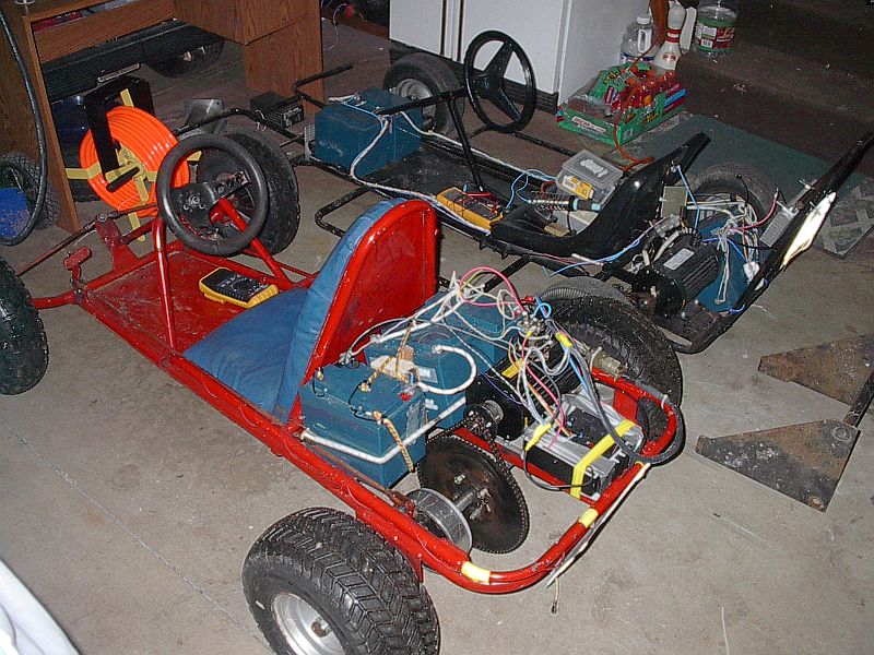
> http://www.qsl.net/w8rnh/gocart/gocart4.jpg
> Thanks,
> Rod
> P.S. Tim has a really cool looking dragster that he
> might bring to Maryland in June for the power of DC.
> Hopefully he can get all of the electronics together
> by then.
>
>
__________________________________________________
Do You Yahoo!?
Tired of spam? Yahoo! Mail has the best spam protection around
http://mail.yahoo.com
--- End Message ---
--- Begin Message ---
Thanks for the good inputs.

a_traction = 0.6 gets me near perfect numbers for a Camaro -- but you
are right with drag radials and/or on a sticky track that should be
higher.

Good point on the trig function, I have a mistake there.

--- Joe Smalley <[EMAIL PROTECTED]> wrote:
> Your a_traction estimates are about 20% conservative.
>
> Using % grade is more common and gets the trig function out of your
> equations.
>
> Rolling drag and Slope compensation should be separate terms.
>
> Using m for mass and meters confuses me. They should be separate
> variables
> with different names.
>
> ===========================================
> I need to go off-line. I hope to comment more later.
>
> Joe Smalley
> Rural Kitsap County WA
> Fiesta 48 volts
> NEDRA 48 volt street conversion record holder
> [EMAIL PROTECTED]


__________________________________________________
Do You Yahoo!?
Tired of spam?  Yahoo! Mail has the best spam protection around
http://mail.yahoo.com
--- End Message ---
--- Begin Message ---
Lee Hart wrote:
...
Hopefully there is a place in Hell for engineers that design things this
way. Their punishment is that they have to replace these heater cores
for eternity (that should be long enough to get a few done :-)
You don't get it Lee - they were *told to* integrate the
heater the most complicated way so service can charge
you for the most labor hours should it brake...
Why should they make *your* life easier? You're not the one
who is [suppose to] work on a vehice, so why bother?
--
Victor
'91 ACRX - something different
--- End Message ---
--- Begin Message ---
John
After all cutting and patching is done, you may realize that you
could be better off just using a water heater designed to work
in electric vehicles with stock cores. MES-DEA is one of the companies
making those - DC input with 100-250VDC and 200-450VDC input ranges;
2, 3, and 4 Kw versions.  Some info is here:
 http://www.metricmind.com/heater_w.htm
More detail (I use it in ACRX):
http://www.metricmind.com/ac_honda/heating.htm
Again, it is more expensive that ceramic core, but everyone I talked to
about it who has done dash removal, saying if they knew what's involved,
they'd just buy it, install in half hour and forget it. All depends
how much your time worth.
I can sell it to you, welcome to consider all above as a plug, but
I'm also happy MES customer myself as well, so recommend the
product as good one.
--
Victor
'91 ACRX - something different
John O'Connor wrote:
...
Thanks Mike,
The factory manual indicated the dash had to be removed. What it didn't
say was that in addition to the dash, the steering column and the entire
ventilation system also has to be disassembled. I did all this back in
February (the parts are all still laid out in the living room) and I
NEVER want to have to do again if I can help it.
All that work is required because the heater core slips into the heater
box from the front of the vehicle. Cutting a hole in the firewall (with
a replaceable cover of some sort maybe) seems to be an elegant way to
provide access in case I need it for repair/replacement of the electric
heater core.
Is there any way to questemate the kind of structural damage I would be
doing by cutting such a hole in the firewall? The vehicle is an 86
Nissan Kingcab Pickup.
John
--- End Message ---
--- Begin Message ---
This is an excellent idea! It didn't even occur to me, but would have
been easier.

--- Doug Weathers <[EMAIL PROTECTED]> wrote:
> I also had a hard time removing the taperlock hub (Electro
> Automotive,
> for aircooled VW) from my 8inch ADC motor while trying to get the
> runout within spec.
>
> After I gave up on the "tap on the bolts with a hammer" technique,
> I
> thought about it for a while and then backed the bolts out so they
> stuck out about a quarter of an inch.  Then I pretended to put the
> flywheel back on.  Tightening the gland nut into the the taperlock
> hub
> squeezed the flywheel back on the heads of the bolts, which pushed
> the
> taper bushing out of the hub.  Worked great.
>
> Oh yeah, to keep the motor shaft from turning, I stuck a big
> screwdriver into the fan blades.  I don't know how good an idea
> this
> is.  I wouldn't recommend doing this if you're bashing on the motor
> shaft or using a lot of torque - you might break a fan blade.


__________________________________________________
Do You Yahoo!?
Tired of spam?  Yahoo! Mail has the best spam protection around
http://mail.yahoo.com
--- End Message ---