                            EV Digest 4358

Topics covered in this issue include:
  1) Re: My project and question
        by Lee Hart <[EMAIL PROTECTED]>
  2) RE: Heat and Charge (Cogeneration?)
        by "Bill Dennis" <[EMAIL PROTECTED]>
  3) Re: Smarts in the US
        by "John Westlund" <[EMAIL PROTECTED]>
  4) Re: Battery box venting
        by Lee Hart <[EMAIL PROTECTED]>
  5) Vicor DC-DC VI-N(B)52-EM (from Halted)
        by Matt Holthausen <[EMAIL PROTECTED]>
  6) Re: Motor Temp (was Re: An update regarding my JeepEV)
        by Nick Viera <[EMAIL PROTECTED]>
  7) Re: new motor
        by "Joe Smalley" <[EMAIL PROTECTED]>
  8) Re: PFC50 for sale
        by "Joe Smalley" <[EMAIL PROTECTED]>
  9) Motor horsepower estimations and questions (Rich, I could use your insight)
        by "John Westlund" <[EMAIL PROTECTED]>
 10) Re: Vicor DC-DC VI-N(B)52-EM (from Halted)
        by "Joe Smalley" <[EMAIL PROTECTED]>
 11) Re: Smarts in the US
        by "Philippe Borges" <[EMAIL PROTECTED]>
 12) Re: Electravan charge connector fix
        by Lee Hart <[EMAIL PROTECTED]>
 13) PFC's and NiMH....
        by Christopher Zach <[EMAIL PROTECTED]>
 14) Re: Inexpensive DC/DC converters
        by "Chris Brune" <[EMAIL PROTECTED]>
 15) Re: PFC's and NiMH....
        by "John G. Lussmyer" <[EMAIL PROTECTED]>
 16) Re: Motor Temp (was Re: An update regarding my JeepEV)
        by Lee Hart <[EMAIL PROTECTED]>
 17) RE: Motor horsepower estimations and questions - some comments
        by "Philip Marino" <[EMAIL PROTECTED]>
 18) TdS Report #32: Team Profile: rEVolutionride.org
        by [EMAIL PROTECTED]
 19) TdS Report #33: Team Profile: Carl Vogel
        by [EMAIL PROTECTED]
--- Begin Message ---
Adams, Lynn wrote:
> Usually a few days over a two week week period in August, of course
> there is always the possiblity of snow in August too...  That's why I
> have both heaters and fans in my battery boxes.

The batteries have so much thermal mass that they only heat/cool perhaps
5 deg.F per day. So a couple days at 100 deg.F might warm them from 70
deg.F to 80 deg.F.
--
"The two most common elements in the universe
are hydrogen and stupidity."    -- Harlan Ellison
--
Lee A. Hart  814 8th Ave N  Sartell MN 56377  leeahart_at_earthlink.net
--- End Message ---
--- Begin Message ---
I'm thinking about giving this a try.  Conceptually, it would look like
this:

220V AC --> 120V Heating Element(s) --> Rectifier/Filter --> 150V (Peak)
Battery Pack --> Ground

By changing the number of heating elements that are paralleled, different
charging amps can be chosen.  Amps will taper as battery pack fills from
100V empty to 150V full.

Is there a good rectifier/filter I can buy that can handle up to 150V and
60A, with minimal DC ripple?

Thanks.

Bill Dennis


Lee Hart wrote:

Here are some notes in case you want to use a water heater as a resistor
for battery testing or charging:

Electric water heaters usually have two heating elements; an upper one
and a lower one. There are also two thermostats; an upper one and a
lower one. The upper one is usually fixed (non-adjustable). The lower
one has the adjustment knob for water temperature.

If the amount of electric power is limited (by the size of your breaker
panel or the breaker and wire size running from it to the water heater),
they wire the two heaters and thermostats so only ONE can be on at a
time. The bottom (adjustable) thermostat has both a normally-open and a
normally-closed switch contact. If the lower t'stat isn't calling for
heat, then it enables the upper t'stat to call for heat. Wired this way,
it (obviously) heats half as fast, but won't blow breakers. The water
heaters usually come wired this way.

If you have lots of power, you can change it to power both elements at
once. It heats twice as fast, but needs twice the breaker and wire size.
They wire them this way for restaurants or other applications where they
use more hot water.

Since there are TWO elements, and one is usually all they use, you can
rewire the upper t'stat and its heating element to use for your EV
resistor. Since you still have a t'stat, it won't overheat. It's just
that the more heat you dump in the top, the less heat the bottom will
supply.

There will be a wider variation in the temperature of the hot water you
get when the heating elements are wired this way. With the top element
never used (bad, for example; or you connected it to your EV charger and
aren't charging it any more), it can take a long time for hot water at
the bottom of the tank to heat the colder water at the top. This problem
is usually tolerable unless your water heater is just barely adequate
as-is (people complain about not enough hot water, or that the
temperature varies too much).

DON'T use the water heater's t'stats on DC!!! They will FAIL FULL-ON!!!
Use the water heater's t'stat on the AC side of the line, not on the DC
side that goes to the batteries.
--
If you would not be forgotten
When your body's dead and rotten
Then write of great deeds worth the reading
Or do the great deeds worth repeating
        -- Ben Franklin, Poor Richard's Almanac
--
Lee A. Hart  814 8th Ave N  Sartell MN 56377  leeahart_at_earthlink.net
--- End Message ---
--- Begin Message ---
Neon John wrote:

>Mercedes and Porsche got very torqued that we civilians
>would dare to
>import a few hundred cars over several years that they
>bought
>themselves a new law back in about 1985.

Damn them. I'd one day like to get an Opel Speedster so I
can shove a 1.9L 209 horsepower 295 lb-ft of torque
turbodiesel from an Opel Vectra in it, dammit! That car
would look so bitchin painted black on black with some black
rims and go like stink while running on vegetable oil...


I'm hoping we will see Smarts in the US soon. I kind of like
their two seat sports car, although the two-tone colors are
kind of tacky, and it does leave a little to be desired in
the looks department. Its roll bar and fast back portions
are very sexy. Would make an excellent EV due to its low
weight, good GVWR, and clean aero. It appears as if about 25
Optimas could be sunk into the floor of that thing for a
cheap way to get 80-100 miles range AC Propulsion style,
under careful driving. A WarP 9'' and Zilla 1k would be
plenty power for a conversion like that. It's strong enough
and appears to have plenty of room under the 'trunk' to fit
a huge battery pack, although without measuring and cutting
into the car there's no way to know for sure. Don't know if
the car would fit the wheelbase requirements though, even if
foreign cars could theoretically be brought over. Just
imagine a Smart Roadster with about 300 pounds of Kokam Li
Poly...
--- End Message ---
--- Begin Message ---
TiM M wrote:
> I'm building new battery boxes for my lead acid cells.
> I was planning on having vent fans that run off the
> charging voltage.

That's a good plan. The fans will then run only while charging. If you
can arrange it, you only need to run the fan at the end of a charge
cycle, so they could be turned on when the voltage reaches a threshold
around 80% charged.

> Do I need to have the ventilation fans run while driving as well?

No, you generally don't need to run the ventilation fans while driving.
The batteries won't gas during discharge unless something is terribly
wrong -- boiling electrolyte, reversed cells, that sort of thing.

> Will hot batteries shorten the life span of lead acid cells?

Yes; the higher the temperature, the shorter the life. However, the
batteries have so much mass that they change temperature very slowly. It
takes DAYS (not hours) for them to acclimate to the surrounding air
temperature. So, you don't have to worry about the peak temperature they
are exposed to; only the long-term average temperature.
--
"The two most common elements in the universe
are hydrogen and stupidity."    -- Harlan Ellison
--
Lee A. Hart  814 8th Ave N  Sartell MN 56377  leeahart_at_earthlink.net
--- End Message ---
--- Begin Message ---
Hello all,
Sorry to bring up this thread again, but I've got a question about one
of the units I ordered.
Very early on I purchased one of these DC-DC converters from Halted and
it sat around for a while. I got around to testing it and it worked
fine after I applied 150v to the input - I immediately got 15v out, and
didn't have to connect anything to any of the six logic terminals.
After this, I decided that I could probably use two of these in my
conversion, so I ordered a second (also from Halted, from the same
listing on their site). This one just arrived today, and it looks
exactly the same, has the same input-output numbers stamped on it (150v
750w in, 15v 600w out) but the model is VI-NB52-EM instead of
VI-N52-EM. I connected the input to the same source that successfully
ran the other one, and...nothing. It gives me a tiny spark when I
connect the (live) input, just like the other one did, but I don't get
anything out of it. Any ideas? I was unable to find exactly what the
'B' meant in any of Vicor's literature. Has anyone else seen reference
to this model?
Thanks,
Matt Holthausen
--- End Message ---
--- Begin Message ---
Hi,
Tom Shay wrote:
The temperature in the tailshaft hole doesn't matter.  Temperature of
 the armature and field windings matter as does the temperature of
the brushes.
The only reason why I measured there was because it was the easiest to
reach location on the motor that was shielded from the wind (the wind
blowing over the probe made all the readings lower).
Rod Hower wrote:
Most EV motors and forklift motors have class H insulation (that's
180 degrees Celsius). If you have a thermocouple mounted IN the
winding I wouldn't go above 150C.
Thanks for the info.
Measuring temperature anywhere besides the brush or winding is
somewhat quesswork since it takes awhile for the temp to propogate
from those locations, especially under heavy load conditions (lots of
big hills).
All I was shooting for was to get an approximate temperature as my motor
does run pretty hot on longer trips (especially in the afternoons when
it is _hot_ out). I just want to be sure I'm not shortening its life,
because if I am I'd look into installing electric fans on it or
something to keep it cooler
You could also mount a sniffer tube :-). You'll smell
those windings cooking before you really do major damage
I sometimes *do* smell a slight, yet noticeable "cooking" smell coming
from the motor once I've parked my Jeep (and the motor no longer has air
circulation). It is the same sort of smell I get when I've just shoved
max current into the motor for a few seconds (like if I throw it in 3rd
gear and floor it at low speeds :-0 ). Maybe it is the brushes making
this smell?
Thanks,
--
-Nick
http://Go.DriveEV.com/
1988 Jeep Cherokee 4x4 EV
---------------------------
--- End Message ---
--- Begin Message ---
Run the motor on about 12 volts for 24 hours to seat the brushes. It is
important to keep the RPM down to a safe level. 12 volts might be too much
for low voltage series motors.

Joe Smalley
Rural Kitsap County WA
Fiesta 48 volts
NEDRA 48 volt street conversion record holder
[EMAIL PROTECTED]

----- Original Message -----
From: "ohnojoe" <[EMAIL PROTECTED]>
To: <[email protected]>
Sent: Friday, May 13, 2005 5:57 AM
Subject: new motor


> I just got my new motor installed in my S-10 (I also have a tracker, which
I
> might be selling soon)
>
> Any tips on breaking in the new motor?
>
> Thanks in advance.
>
> Joe
>
>
--- End Message ---
--- Begin Message ---
It was designed for a 360 Volt PACK.
The design called for going up to 450 Volts.
Some chargers were shipped capable of going to 525 Volts.

The part number indicates it is a Buck Enhanced model (the B in the part
number).

The H in the part number MAY indicate it is a high voltage capable unit.

Since the serial number is included in the description, Rich Rudman may be
able to shed some light on the configuration and history of this unit.

Joe Smalley
Rural Kitsap County WA
Fiesta 48 volts
NEDRA 48 volt street conversion record holder
[EMAIL PROTECTED]


----- Original Message -----
From: "Christopher Zach" <[EMAIL PROTECTED]>
To: <[email protected]>
Sent: Friday, May 13, 2005 7:33 PM
Subject: Re: PFC50 for sale


> Hm. Is 360 volts the peak for a PFC-50? Or can it go into the mid 400's?
>
> Chris
>
> Rod Hower wrote:
> > Ebay item #7974246964
> > I wonder who is selling this?
> > Starting bid of $1000
> >
>
--- End Message ---
--- Begin Message ---
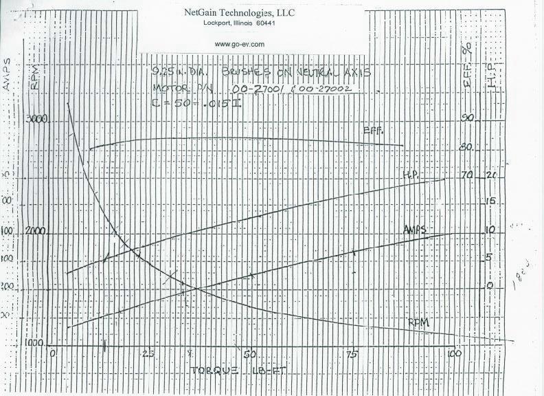
I remember Rich commenting about an 8'' motor that you can
get 200 horsepower from and 200 lb-ft of torque both at
about 5,000 rpm. What modifications did you do to that
motor, what voltage and currents were you putting in it, and
what kind of horsepower was it making at higher rpm levels
like around 7,000 or 8000 rpm?

I'd like to use as small a motor as possible while keeping
as much power as possible, in order to shave weight some and
save a little room. I'm still undecided between a WarP 9'',
WarP 8'', and an XP1227-A. Leaning toward the 9'' until I
find out more.


I conducted an estimation on the 9'' from the curve provided
on Netgain's website, using the same method found from J.
Russell Lemon�s EV simulation guide, which can be found
here:

http://home.att.net/~NCSDCA/EVAoSD/evsim.htm

Basically, for the motor, I had to look at the torque curve,
and construct a differential equation that would represent
it on a max possible allowed torque(no regard to a current
limitation by controller) vs. max motor voltage vs. rpm.

max theoretical torque = 350*(max voltage)^3/(rpm^2)-3

Then I also had to construct one for torque vs. amps, the
estimation counting in back emf:

limited torque = (max motor amps - 61)/4


Thus, as long as max theoretical torque > limited torque at
a certain rpm, the controller limited torque would be the
torque at that rpm, and at any rpm after the point where max
theoretical torque = limited torque, then the max
theoretical torque at that motor voltage and rpm would be
the torque at that rpm.

The WarP 9'' is rated at 192V by Netgain. I used that
voltage for my simulation. I'm going to use a 300V Zilla 1k
to keep torque down so I don't kill my differential or
transmission(along with cost down), and don't want more than
about 250 lb-ft, so max motor amps is about 1,000. A 300V
pack of Optima D750 YTs wouldn't have to worry about voltage
sag under highest allowed power, under ideal conditions, as
voltage sag wouldn't be a limiting factor for the amount of
power that gets to the motor.


Thus, I get the following results for simulating throttle to
the floor, torque and horsepower being the figures at the
flywheel:

MotorRPM...MotorTorque(lb-ft)...MotorHorsepower

0...235...0
500...235...22
1000...235...45
1500...235...67
2000...235...89
2500...235...112
3000...235...134
3228...235...144 ***motor peak horsepower***
3500...199...133
4000...152...116
4500...119...102
5000...96...91
5500...79...83
6000...66...75
6500...56...69
7000...48...63
7500...41...59
8000...36...54 ***motor redline***
8500...31...51
9000...28...47

MotorCurrent(amperes)...MotorTorque(lb-ft)

100...10
150...22
200...35
250...47
300...60
350...72
400...85
450...97
500...110
550...122
600...135
650...147
700...160
750...172
800...185
850...197
900...210
950...222
1000...235


As you can see, there is a linear relationship between
torque and current, to account for backemf, although without
backemf, the torque of a series DC motor is proportional to
the square of the current.(Hence the equation T = k*i^2,
which IIRC, doesn't account for back emf)

In this simulation, the voltage starts at 0 and rises
linearly to 192V at the time peak horsepower is reached,
then the torque and current taper off while staying at 192V.
Does this seem correct?

This simulation almost matches Netgain's graph perfectly
from the 0-400 amp plot they give as far as current vs.
torque is concerned.

http://www.go-ev.com/images/warp9_curves.jpg


Does this estimate look reasonably accurate? I resorted to
this method because I don't exactly trust the constants
provided on Uve's EV page, especially when trying to
estimate unknown territory for DC motors at around 1,000
amps or so.

Does this power curve seem inaccurate? Underestimated, or
overestimated?

What about running a WarP 9'' at 192V? It is rated at that
voltage by Netgain, but would bad things happen if it were
to be run at that voltage and with 1,000 amps shoved through
it, even after broken in? Could it be safely run at a higher
voltage, like, maybe 216V?

I'd prefer my peak horsepower at higher rpm if it meant
sacrificing torque, as I'm not going to be able to use more
than 250 lb-ft anyway, as that will pose a risk of breaking
tranny/diff, and I want those portions of the car to stay
Triumph components. Installed are transmission and
differential from Triumph TR6, which according to various
Triumph racers I talked to, it will be able to handle about
200 horsepower and about 250 lb-ft without excessive wear or
stripping. Plus having peak horsepower at a higher RPM means
higher top speed, and I'd like to have that since I won't be
able to make use of more than 250 lb-ft.


Could any racers give me their thoughts on this? How about
recommendations?

If I could save 40 pounds using a WarP 8'' motor and get
more than 140 horsepower by adjusting brush timing, that
would be swell. The higher rpm I can get peak power at, and
the higher motor volts I can push through the motor, the
better. I know series DC electric motors are good for low
end peak power and have a power curve like a mountain, but I
cannot help but wonder what kinds of higher end horsepower
figures can be achieved, especially with Wayland estimating
175 horsepower from his ADC9'' at 204 max motor volts and
1000 max motor amps for Blue Meanie's upgrade. 175+
horsepower in the ~2600 pound EV I'm planning would be
batshit insane. 200 horsepower with about the same amount of
torque would be the sweet spot I'm looking for.
--- End Message ---
--- Begin Message ---
I may have a clue for you...

The VI-N52-EM data sheet is at
http://www.vicorpower.com/documents/datasheets/ds_megamod.pdf

The VI-BXXX module is described on sheet 10 (page 3-1) of the applications
manual at
http://www.vicr.com/documents/applications_manual/apps_manual.pdf

The B modules have no control circuitry, they need to be clocked by a driver
module.

Joe Smalley
Rural Kitsap County WA
Fiesta 48 volts
NEDRA 48 volt street conversion record holder
[EMAIL PROTECTED]


----- Original Message -----
From: "Matt Holthausen" <[EMAIL PROTECTED]>
To: <[email protected]>
Sent: Friday, May 13, 2005 10:00 PM
Subject: Vicor DC-DC VI-N(B)52-EM (from Halted)


> Hello all,
> Sorry to bring up this thread again, but I've got a question about one
> of the units I ordered.
> Very early on I purchased one of these DC-DC converters from Halted and
> it sat around for a while. I got around to testing it and it worked
> fine after I applied 150v to the input - I immediately got 15v out, and
> didn't have to connect anything to any of the six logic terminals.
>
> After this, I decided that I could probably use two of these in my
> conversion, so I ordered a second (also from Halted, from the same
> listing on their site). This one just arrived today, and it looks
> exactly the same, has the same input-output numbers stamped on it (150v
> 750w in, 15v 600w out) but the model is VI-NB52-EM instead of
> VI-N52-EM. I connected the input to the same source that successfully
> ran the other one, and...nothing. It gives me a tiny spark when I
> connect the (live) input, just like the other one did, but I don't get
> anything out of it. Any ideas? I was unable to find exactly what the
> 'B' meant in any of Vicor's literature. Has anyone else seen reference
> to this model?
>
> Thanks,
>
> Matt Holthausen
>
--- End Message ---
--- Begin Message ---
:^)  you can't put 25 optima in a smart, maybe 12... pressing them :^)

Philippe

Et si le pot d'�chappement sortait au centre du volant ?
quel carburant choisiriez-vous ?
 http://vehiculeselectriques.free.fr
Forum de discussion sur les v�hicules �lectriques
http://vehiculeselectriques.free.fr/Forum/index.php


----- Original Message -----
From: "John Westlund" <[EMAIL PROTECTED]>
To: <[email protected]>
Sent: Saturday, May 14, 2005 5:34 AM
Subject: Re: Smarts in the US


> Neon John wrote:
>
> >Mercedes and Porsche got very torqued that we civilians
> >would dare to
> >import a few hundred cars over several years that they
> >bought
> >themselves a new law back in about 1985.
>
> Damn them. I'd one day like to get an Opel Speedster so I
> can shove a 1.9L 209 horsepower 295 lb-ft of torque
> turbodiesel from an Opel Vectra in it, dammit! That car
> would look so bitchin painted black on black with some black
> rims and go like stink while running on vegetable oil...
>
>
> I'm hoping we will see Smarts in the US soon. I kind of like
> their two seat sports car, although the two-tone colors are
> kind of tacky, and it does leave a little to be desired in
> the looks department. Its roll bar and fast back portions
> are very sexy. Would make an excellent EV due to its low
> weight, good GVWR, and clean aero. It appears as if about 25
> Optimas could be sunk into the floor of that thing for a
> cheap way to get 80-100 miles range AC Propulsion style,
> under careful driving. A WarP 9'' and Zilla 1k would be
> plenty power for a conversion like that. It's strong enough
> and appears to have plenty of room under the 'trunk' to fit
> a huge battery pack, although without measuring and cutting
> into the car there's no way to know for sure. Don't know if
> the car would fit the wheelbase requirements though, even if
> foreign cars could theoretically be brought over. Just
> imagine a Smart Roadster with about 300 pounds of Kokam Li
> Poly...
>
--- End Message ---
--- Begin Message ---
Lawrence Rhodes wrote:
> OK I think I found a solution for the 4 prong connector and safety
> for shock. I replaced the Hubbel with a Bryant 71530NC and
> associated flanged recessed male. ($130 for both yikes) The safety
> switch was a little harder...

Sounds like you have a workable solution, Lawrence.

Here's another approach that is fairly easy to implement. If the housing
is mostly non-ferrous (not steel), you can drill a hole and epoxy in a
magnet into the cord-mounted connector. Then put a reed switch on the
outside of the receptacle, next to where the magnet is when mated. Now
the reed switch will close when the magnet is present. The reed switch
can control power to the coil of a relay or contactor, whose contacts
can prevent "drive-aways" or connect the pack to the connector, etc.
--
"The two most common elements in the universe
are hydrogen and stupidity."    -- Harlan Ellison
--
Lee A. Hart  814 8th Ave N  Sartell MN 56377  leeahart_at_earthlink.net
--- End Message ---
--- Begin Message ---
Ok, as some people know I bought a pile of Panasonic Prismatic batteries
to take a look at the Prismatic cells and see if they can be used as a
traction pack. Yes it's insane in a way, but since there is no other
NiMH batteries on the market that's what we're stuck with.
So far the batteries are very nice. 6 cells to a battery, 7.2 volts each
nominal, 6.5ah capacity. They can handle high current loads (30-60amps)
without falling apart. Which makes sense; they were designed for that.
The key of course is charging: How do you monitor charge to make sure
that they don't blow up. Especially given that NiMH need dv/dt, delta V,
time limits, two stage+trickle charging, and all that sort of stuff.
Currently I'm working with the TI BQ400 series chipsets to handle this.
Nice chip; it can monitor cell temp, voltage, deltas, time, and has a
timer circuit that can be set as a deadman control. And I do all that
right now (including temp sensors for the delta T detection) Output is
currently gated to a small MOSFET based switcher charger with a limit of
3amps. Even has a little frob to allow an external load to be applied
for a discharge/charge circuit.
Problem is the current charger can only handle 3 amps. What I would
really like is a constant current charger that can be gated by this
chipset to charge the batteries at something more like 6-20 amps. And if
I go with a string of batteries I will need something that can handle in
the 400 volt range*
Any thoughts on intermediate sized chargers that can be controlled by an
external controller?
Chris
*For a pack larger than 36 volts one solution would be to use a DQ every
36 volts to monitor the local battery region, then signal a Basic STAMP
via optoisolators. THe STAMP can then monitor all the batteries, and
signal the charger to switch modes based on the results of any/all of
the DQ400's.
Joe Smalley wrote:
It was designed for a 360 Volt PACK.
The design called for going up to 450 Volts.
Some chargers were shipped capable of going to 525 Volts.
--- End Message ---
--- Begin Message ---
Hi John,
The datasheet for the SD350 family indicates that it come in one of 3 input
voltage variants:
B:  19-36, C:  36-72, D:  72-144.  Each of these three input ranges covering
the 2:1 input range they quote.
If you have a 72V system you might expect that your actual battery pack
voltage would vary from around 60 volts to about 90V.
Thus I don't see where one of the specified input ranges would cover your
needs.
I would also comment that you need to be careful about these types of power
supplies.  They aren't designed to be mounted on a vehicle.  They won't be
protected against water intrusion.  If you leave your converter connected
all the time does the fan run all the time?

There are companies out there that make converters designed for 72V on
vehicle operation.

Regards,
Chris

----- Original Message -----
From: "Neon John" <[EMAIL PROTECTED]>
To: <[email protected]>
Sent: Friday, May 13, 2005 2:12 PM
Subject: Inexpensive DC/DC converters


> I've been pondering a 72/12 volt solution for my Citi and
> coincidentally the new Astrodyne power supply catalog came in.  They
> have some new products that are right down our alley and very
> affordable.
>
> The first is the SD350 350 watt inverter.
> http://www.astrodyne.com/astro/product_main_matrix.asp?dept_id=6&watts=86
> Data sheet here:
> http://datasheet.astrodyne.com/SD350.pdf
>
> This inverter family is available with a DC input range of 19 to 144
> volts.  Output is adjustable from 11 to 16 volts at 27.5 amps.  $129
> in single piece quantities, $119 for 10.
>
> I just got off the phone with an application engineer.  One of my
> questions was whether this 144 volt rating is working or max.  He said
> that it could probably withstand 10% more than the rating.
>
> For higher voltages he recommended the AC/DC converter lines that will
> run on DC input.  This is similar to the Lambda supplies but cheaper.
> The SP series will accept up to about 375vdc, minimum of about 120
> vdc.  They're available in ratings up to 1500 watts (100 amps out).  A
> 320 watt unit (22 amps) is $149.  These can be operated in parallel.
> The PSP series has an extra terminal to force load sharing for
> parallel operation.
>
> I've just ordered an SP350 for my Citi.  I'll report on its operation.
>
> Meanwhile, considering the good discount on quantity, someone here
> might consider organizing a group buy.
>
> John
> ---
> John De Armond
> [EMAIL PROTECTED]
> http://www.johngsbbq.com
> Cleveland, Occupied TN
>
--- End Message ---
--- Begin Message ---
At 06:16 AM 5/14/2005, Christopher Zach wrote:
Problem is the current charger can only handle 3 amps. What I would really
like is a constant current charger that can be gated by this chipset to
charge the batteries at something more like 6-20 amps. And if I go with a
string of batteries I will need something that can handle in the 400 volt
range*
For my LiIon tests, I was controlling my PFC-20 via the RegBus line.
--
John G. Lussmyer      mailto:[EMAIL PROTECTED]
Dragons soar and Tigers prowl while I dream....
http://www.CasaDelGato.com
--- End Message ---
--- Begin Message ---
Nick Viera wrote:
> All I was shooting for was to get an approximate temperature as
> my motor does run pretty hot on longer trips (especially in the
> afternoons when it is _hot_ out).

Is it an Advanced DC motor? Many of them have a switch buried in the
field winding. If you see two small wires coming out the side, that's
it. This switch will close if the winding gets too hot.

> I sometimes *do* smell a slight, yet noticeable "cooking" smell
> coming from the motor once I've parked my Jeep (and the motor no
> longer has air circulation). It is the same sort of smell I get
> when I've just shoved max current into the motor for a few seconds
> (like if I throw it in 3rd gear and floor it at low speeds :-0 ).
> Maybe it is the brushes making this smell?

No, it is hot insulation. If you smell it, you probably *are* running
the motor too hot.

Are you depending entirely on the motor's internal fan for cooling? If
so, remember that this fan only works at high rpm. "Flooring it" in 3rd
gear forces the motor to draw maximum current at minimum rpm, so it
isn't getting enough cooling. You need to shift to keep motor rpm HIGH
on an EV; not low like an ICE!

If you insist on driving at high current and low rpm, then you'll need
to add an external blower to cool the motor.
--
"Never doubt that the work of a small group of thoughtful, committed
citizens can change the world. Indeed, it's the only thing that ever
has!" -- Margaret Mead
--
Lee A. Hart  814 8th Ave N  Sartell MN 56377  leeahart_at_earthlink.net
--- End Message ---
--- Begin Message ---
John -
It's good to see some serious analysis and planning before making a decision
like this. This kind of analysis always ends up more complex than it starts
out. And, even if the final results don't give you exact predictions, it
makes you think about what is really happening, and how your choices affect
the result.
I've got a few comments and questions - I'll insert them into your post:
From: "John Westlund" <[EMAIL PROTECTED]>
Reply-To: [email protected]
I'd like to use as small a motor as possible while keeping
as much power as possible, in order to shave weight some and
save a little room. I'm still undecided between a WarP 9'',
WarP 8'', and an XP1227-A. Leaning toward the 9'' until I
find out more.
I had to make a similar decision for a very different car - a small, light,
low power commuter conversion ( an Echo). My choice was between an ADC 6.7"
and ADC 8 ". I chose the 8" because the significantly lower efficiency of
the 6.7" ( at the typical currents I expected to use) meant that I would
have reduced power and range. The higher efficiency of the larger motor more
than made up for the extra weight. You may also find that the larger motor
is a better choice in your case, for the same reason.
Your analyses of both motors may show that and lead you to the same
conclusion. BUT, the benefit of the larger motor may only become apparent
if you look at real data at high currents. It may not show up if you just
use the manufacturers' data at 400 amps and below.
I conducted an estimation on the 9'' from the curve provided
on Netgain's website, using the same method found from J.
Russell Lemon�s EV simulation guide, which can be found
here:
http://home.att.net/~NCSDCA/EVAoSD/evsim.htm
Basically, for the motor, I had to look at the torque curve,
and construct a differential equation that would represent
it on a max possible allowed torque(no regard to a current
limitation by controller) vs. max motor voltage vs. rpm.
These are not differential equations. Differential equations relate the
rates of changes of values such as voltage, torque, or RPM, or current.
An example of a differential equation is I = C * dv/dt. This says that the
current through a capacitor equals the value of the capacitor times the rate
of change of voltage across it. ( "dv/dt" is the rate of change of voltage
vs time at any instant).
Your equations give the relationships between motor values at any given
time. ( Useful and necessary - just not "differential equations")
max theoretical torque = 350*(max voltage)^3/(rpm^2)-3
Then I also had to construct one for torque vs. amps, the
estimation counting in back emf:
The relationship of torque and current in a series motor, as for as I know,
has nothing to do with back EMF. This relationship is independent of
voltage and RPM. The voltage and motor RPM will determine what the motor
current will be, but, once you know the motor current, that is all you need
to predict the torque. SO, by not including RPM in your torque vs current
equation, you are not losing anything in accuracy.
limited torque = (max motor amps - 61)/4
What you have done here is fit a straight line to the current torque curve.
( It will only match the original curve at two points)
It's a crude fit, at best, and will probably not hold true very well at all
for values well beyond the original curve you used to get this straight
line.
As an example of this, your equation says that this motor will produce no
torque at 61 amps. ( If you set the motor amps to 61 in your equation, the
torque is zero).
This may indeed by true, but the zero-torque current for most ADC series
motors ( that is, the current they draw with not torque at the shaft
{nothing connected to the shaft}) is usually about 25-30 amps.
It looks like (from the motor curve) that the actual zero-torque current for
this motor is about 40 amps. The small error ( 40 compared to 60) is the
result of the limited-accuracy straight-line curve fit.
To get a better current torque relationship, you need some real data at the
high current levels you expect to use. (Rich - or other high-power guys -
may be good sources for this data). Then , you could try to fit the wider
-range curve with a more complex curve. Even if you stay with a
straight-line fit, if you fit it to a real data curve that goes up to, say,
1000 amps, that would really improve your accuracy.
Another choice would be to use two straight-line fits - one for the lower
part of the curve ( for example, current less than 500 amps) and another for
the high-current portion. Then , in your calculations, just use whichever
curve fits the current at that time.
Thus, as long as max theoretical torque > limited torque at
a certain rpm, the controller limited torque would be the
torque at that rpm, and at any rpm after the point where max
theoretical torque = limited torque, then the max
theoretical torque at that motor voltage and rpm would be
the torque at that rpm.
The WarP 9'' is rated at 192V by Netgain. I used that
voltage for my simulation. I'm going to use a 300V Zilla 1k
to keep torque down so I don't kill my differential or
transmission(along with cost down), and don't want more than
about 250 lb-ft, so max motor amps is about 1,000. A 300V
pack of Optima D750 YTs wouldn't have to worry about voltage
sag under highest allowed power, under ideal conditions, as
voltage sag wouldn't be a limiting factor for the amount of
power that gets to the motor.
Sag might not be a factor, but the pack voltage is. The maximum torque is
controller ( current) limited. But, the higher the available (battery)
voltage, the higher the motor RPM at which you can supply this
current-limited maximum torque, so the higher the peak horsepower. And, the
horsepower will be higher at any RPM above the now-higher max-power RPM.
That's because the higher available voltage can drive more current through
the motor ( resulting in more torque, and more HP) even above the current
limit.
Thus, I get the following results for simulating throttle to
the floor, torque and horsepower being the figures at the
flywheel:
MotorRPM...MotorTorque(lb-ft)...MotorHorsepower
0...235...0
500...235...22
1000...235...45
1500...235...67
2000...235...89
2500...235...112
3000...235...134
3228...235...144 ***motor peak horsepower***
3500...199...133
4000...152...116
4500...119...102
5000...96...91
5500...79...83
6000...66...75
6500...56...69
7000...48...63
7500...41...59
8000...36...54 ***motor redline***
8500...31...51
9000...28...47
MotorCurrent(amperes)...MotorTorque(lb-ft)
100...10
150...22
200...35
250...47
300...60
350...72
400...85
450...97
500...110
550...122
600...135
650...147
700...160
750...172
800...185
850...197
900...210
950...222
1000...235
As you can see, there is a linear relationship between
torque and current, to account for backemf, although without
backemf, the torque of a series DC motor is proportional to
the square of the current.(Hence the equation T = k*i^2,
which IIRC, doesn't account for back emf)
I would not call this a "linear relationship". That implies that the torque
and current are proportional, and they are not, according to your equation
( and table). That is because of your offset term of 61 amps. The actual
relationship is somewhere between linear and quadratic ( proportional to the
square), and, it will probably do weird things at very high currents due to
magnetic saturation effects.
In this simulation, the voltage starts at 0 and rises
linearly to 192V at the time peak horsepower is reached,
then the torque and current taper off while staying at 192V.
Does this seem correct?
This simulation almost matches Netgain's graph perfectly
from the 0-400 amp plot they give as far as current vs.
torque is concerned.
http://www.go-ev.com/images/warp9_curves.jpg
Does this estimate look reasonably accurate? I resorted to
this method because I don't exactly trust the constants
provided on Uve's EV page, especially when trying to
estimate unknown territory for DC motors at around 1,000
amps or so.
Does this power curve seem inaccurate? Underestimated, or
overestimated?
What about running a WarP 9'' at 192V? It is rated at that
voltage by Netgain, but would bad things happen if it were
to be run at that voltage and with 1,000 amps shoved through
it, even after broken in? Could it be safely run at a higher
voltage, like, maybe 216V?
I'd prefer my peak horsepower at higher rpm if it meant
sacrificing torque, as I'm not going to be able to use more
than 250 lb-ft anyway, as that will pose a risk of breaking
tranny/diff, and I want those portions of the car to stay
Triumph components. Installed are transmission and
differential from Triumph TR6, which according to various
Triumph racers I talked to, it will be able to handle about
200 horsepower and about 250 lb-ft without excessive wear or
stripping. Plus having peak horsepower at a higher RPM means
higher top speed, and I'd like to have that since I won't be
able to make use of more than 250 lb-ft.
The way to get peak HP at higher RPM , other than to rewind the motor, is to
use a higher maximum voltage. (See my earlier comments)
Could any racers give me their thoughts on this? How about
recommendations?
If I could save 40 pounds using a WarP 8'' motor and get
more than 140 horsepower by adjusting brush timing, that
would be swell.
Again - be sure that the 40 pounds saving is worth the loss in efficiency,
which might be equivalent to losing an entire battery ( or more).
The higher rpm I can get peak power at, and
the higher motor volts I can push through the motor, the
better. I know series DC electric motors are good for low
end peak power and have a power curve like a mountain, but I
cannot help but wonder what kinds of higher end horsepower
figures can be achieved, especially with Wayland estimating
175 horsepower from his ADC9'' at 204 max motor volts and
1000 max motor amps for Blue Meanie's upgrade. 175+
horsepower in the ~2600 pound EV I'm planning would be
batshit insane. 200 horsepower with about the same amount of
torque would be the sweet spot I'm looking for.
Phil
_________________________________________________________________
Don�t just search. Find. Check out the new MSN Search!
http://search.msn.click-url.com/go/onm00200636ave/direct/01/
--- End Message ---
--- Begin Message ---
TdS Report #32: Team Profile: rEVolutionride.org

Two years ago this team from North Haven Island off the course of Maine
brought thier electric driven van to the Tour, and talked about efforts to make
the island more energy independent and efficient.  Ben Lovell brought me up to
date.

"We did a few minor maintenance projects on the van to keep it going.  We
haven't made any major modifications to the vehicle itself.  We added anti-sway
bars and some things like that."

The battery pack is 108 Volts of Trojan flooded blocks.  The Curtis controller
and other power electronics is very neatly wired under a ventelated clear
plastic cover in the rear.  It is very pretty to my eye.  You can read the
wiring very easily.  The van also has a single solar panel on the roof.

"Mostly, for the past two years, we've been setting up a system at our school
to be zero-emissions.  We don't use any electricity from the regular power
supply."  The island gets its electricity through an undersea cable.  "We've
set up a 5.1 kiloWatt solar array of the school, and have a net-metering
agreement with Fox Island Electric Cooperative."  Net-metering allows them to
sell power back to the electric company for the same price as they pay to get
it.  "Whenever we don't use the electricity to charge the vehicle, it goes back
to the grid."

There was a lot of planning that went into this project.  They were talking
about it when they were last at the Tour.  The panels were put on the roof of
the school about two months ago.

Between Tours, the van is used to run errands around the island.  "We have a
small bus, but it's too big to use on the island.  Anywhere you have to go is
no more that 12 miles.  So we just all pile in the van and go to the beach for
science class or whatever.  It gets used more than once most days.  The
superintendent uses it to pick people up at the boat and travel around the
island.


John Dietter is a teacher at the North Haven community school and advisor to
rEVolutionride and the solar panel project.

"These students had written a grant proposal to purchase a photovoltaic system
for the school.  Fox Island Electric had also written a grant to the Department
of Energy to install photovoltaic systems on North Haven and the other island
near us.  The two of use came together, combined our grants, and were able to
purchase more capacity than the sum of our individual proposals."  Now
identical systems are on both islands.  "Their installer came out and worked
with our students.  That saved a lot on installation."

They have a poster with photos of the students on the roof with the installer.
The students are wearing safety harnesses.  "The local construction company
donated the harnesses and had their safety coordinator teach us how to use
them."

Ben was one of the students on the roof.  It took less than two days to install
the panels.  "Our original design had batteries to provide power during power
outages.  But we eliminated those."


To top it off, the van is being charged during the Tour using biodiesel fuel
that they brought with them.  They make the fuel from waste cooking oil from
the restaurant on the island.  This had been a demonstration project for some
time, but they started to make large batches this spring.

 -      -       -       -
 The complete set of Tour de Sol Reports for 2005 can be found at:
             http://www.AutoAuditorium.com/TdS_Reports_2005
 The complete set of past Tour de Sol Reports can be found at:
             http://www.FovealSystems.com/Tour_de_Sol_Reports.html
 -      -       -       -
 The above is Copyright 2005 by Michael H. Bianchi.
 Permission to copy is granted provided the entire article is presented
 without modification and this notice remains attached.
 For other arrangements, contact me at  +1-973-822-2085 .
 -      -       -       -
 For more on the NESEA Tour de Sol, see the web page at
                        http://www.TourdeSol.org
 -      -       -       -
 Official NESEA Tour de Sol information is available from the sponsor,
 the Northeast Sustainable Energy Association (NESEA) at
  413 774-6051 , and  50 Miles Street, Greenfield, MA 01301 , and
  [EMAIL PROTECTED] .  All media enquiries should be addressed to ...

        Jack Groh
        Tour de Sol Communications Director
        P.O. Box 6044
        Warwick, RI  02887-6044

        401 732-1551
        401 732-0547 fax
        [EMAIL PROTECTED]
--- End Message ---
--- Begin Message ---
TdS Report #33: Team Profile: Carl Vogel

Carl, from West Babylon, New York, has become a regular at the Tour de Sol.
His Vogelbilt motorcycle always got attention, and he has returned with a newer
version, plus his biodiesel powered truck.

This is not the bike we saw before.  "This is my second bike.  It went cross
country with the TV series, formerly called EcoTrekker, now called the Cool
Fuel Road Trip that will air this September."  He isn't sure which cable
channel it will be on; possibly Discover or The Learning Channel.

Doing anything for the second time allows one to learn from the previous
experience.  "The frame changed.  I can get the 10 batteries out very quickly.
The other bike took about two hours.  The rear suspension is changed a bit.
The first had a chain drive; this uses toothed belts."  A 6 inch Advanced DC
motor drives a 5-speed transmission via a belt, which in turn drives the rear
wheel.  "I tend to use the first 4 gears only.  I can get about 60 miles."
The Zappy controller gives the bike regenerative braking and a reverse.  "It
has worked flawlessly.  I'm very happy with it."

His Ford 250 SuperDuty truck is now 13 months old has been run B100 biodiesel
since day one.  52,000 miles later it has been to California and all over the
place.  "I had to pick my route out west to get biodiesel."  When he could not
get it he would use a mix until he found it again.  No changes were required to
switch fuels.  The truck has a 95 auxillary tank plus the 40 gallon stock tank.
The truck is used to deliver biodiesel fuel to Carl's customers on Long Island.
The fuel is manufactured on Long Island using virgin soybean oil.

Carl volunteers his time at Farmdale College on Long Island, working on fuel
cells and other electric vehicles.

 -      -       -       -
 The complete set of Tour de Sol Reports for 2005 can be found at:
             http://www.AutoAuditorium.com/TdS_Reports_2005
 The complete set of past Tour de Sol Reports can be found at:
             http://www.FovealSystems.com/Tour_de_Sol_Reports.html
 -      -       -       -
 The above is Copyright 2005 by Michael H. Bianchi.
 Permission to copy is granted provided the entire article is presented
 without modification and this notice remains attached.
 For other arrangements, contact me at  +1-973-822-2085 .
 -      -       -       -
 For more on the NESEA Tour de Sol, see the web page at
                        http://www.TourdeSol.org
 -      -       -       -
 Official NESEA Tour de Sol information is available from the sponsor,
 the Northeast Sustainable Energy Association (NESEA) at
  413 774-6051 , and  50 Miles Street, Greenfield, MA 01301 , and
  [EMAIL PROTECTED] .  All media enquiries should be addressed to ...

        Jack Groh
        Tour de Sol Communications Director
        P.O. Box 6044
        Warwick, RI  02887-6044

        401 732-1551
        401 732-0547 fax
        [EMAIL PROTECTED]
--- End Message ---