Part is MMBT3904
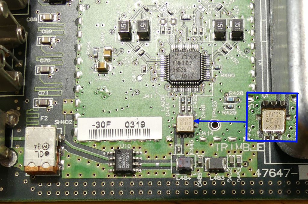
> On Aug 4, 2017, at 5:39 PM, Chris Waldrup <kd4...@gmail.com> wrote:
>
> Sorry. Should have changed subject line before. Just changed it.
>
> The EEV blog link shows the transistors but it's too fuzzy to read SMT part
> markings. If I can get a code I'll try and look it up online.
>
> Thank you.
>
> Chris
>
>> On Aug 4, 2017, at 5:27 PM, Chris Waldrup <kd4...@gmail.com> wrote:
>>
>> Thanks guys.
>> I've opened up my T bolt and noticed a SOT23 packaged part has the top blown
>> off.
>> The PPS BNC jack has U19 beside it.
>> The next part is blown. Could someone take a closeup of the five parts
>> around U19?
>> The intact parts are marked:
>> 5Dz
>> 1AM
>> and two 2Az parts.
>>
>>
>> Chris
>>
>>> On Aug 4, 2017, at 4:13 PM, Arthur Dent <golgarfrinc...@gmail.com> wrote:
>>>
>>> Actually that isn't my photo I linked to but one I just Googled. That is
>>> probably a board revision most people don't have but it was the first one
>>> I saw so I used it just to show that the GPS receiver is part of the
>>> only circuit board and not another easily replaceable board like in some
>>> other units.
>>>
>>> I just took a couple of photos of the later revision of the board for
>>> anyone interested in seeing what might be fried. In the photo of the
>>> top of the board the signal comes into a filter then to a 25db amp
>>> marked AM50002 by Macom. Above the filter near the input is where the
>>> decoupled +5VDC for the antenna is connected. If you are only reading
>>> 0.5VDC, if your're lucky it might only be the amp is fried and that
>>> could be an easy fix. If the 5VDC is ok with the amp input pin lifted,
>>> it might be the only problem. I wouldn't bet on it though. The 4031 I
>>> believe is a 1575.42 SAW filter
>>>
>>> The photo of the bottom of the receiver area shows a Sawtek filter and
>>> other parts. At the bottom of the photo is C460, a feedthrough capacitor
>>> and that might be where the receiver output is but where my Tbolts are
>>> working I don't feel the need to look into whether you could connect
>>> the output of a seperate GPS receiver there to make it work.
>>>
>>> I do have one Tbolt that has no oscillator. I brought the EFC and 10Mhz
>>> connections to SMA connectors on the back so I can test other oscillators
>>> or GPSDOs that don't have an easy way to monitor of graph the stability
>>> of those units and using Lady Heather gives me a good way to compare the
>>> graphs to ones I'm used to. You might possibly be able to replace the
>>> built-in receiver but it might be easier to buy a working Thunderbolt.
>>>
>>>
>>> http://i906.photobucket.com/albums/ac262/rjb1998/GPS%20top%201_zpslgxunnyw.jpg
>>>
>>> http://i906.photobucket.com/albums/ac262/rjb1998/GPS%20bottom%201_zpschvruppt.jpg
>>> _______________________________________________
>>> time-nuts mailing list -- time-nuts@febo.com
>>> To unsubscribe, go to
>>> https://www.febo.com/cgi-bin/mailman/listinfo/time-nuts
>>> and follow the instructions there.
_______________________________________________
time-nuts mailing list -- time-nuts@febo.com
To unsubscribe, go to https://www.febo.com/cgi-bin/mailman/listinfo/time-nuts
and follow the instructions there.