); SAEximRunCond expanded to false
Errors-To: [EMAIL PROTECTED] RETRY

In a message dated 11/7/2007 14:40:04 Pacific Standard Time,
[EMAIL PROTECTED] writes:
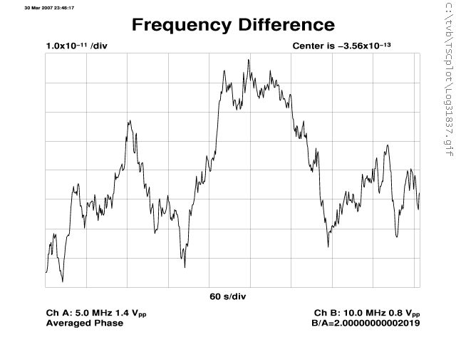
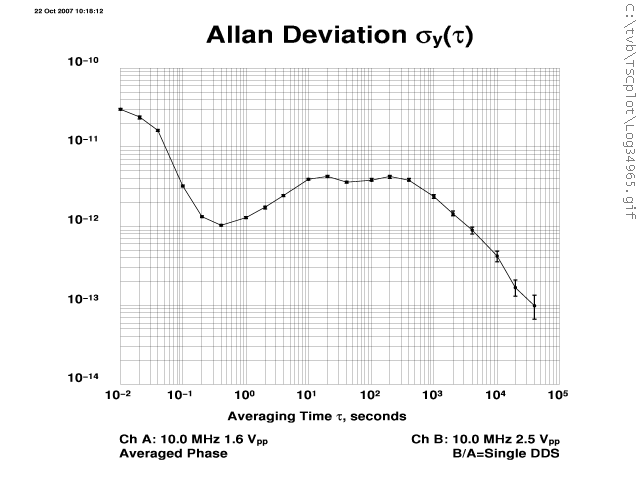
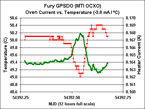
>Thanks. Here's my math. An average 10 MHz OCXO has an
>EFC  range of, say, 1e-7 over 10 V. That's 1e-8/V; 1e-11/mV.

>Now look at  the short-term frequency error of a  Fury:
>http://www.leapsecond.com/pages/fury/log31837v.gif
>( from  http://www.leapsecond.com/pages/fury/ )

>You see Fury frequency  varies by at least 5e-11 over minutes,
>as is normal for this class of  OCXO. To make that much noise
>with EFC effects alone you'd need on the  order of 5000 uV
>variation on EFC line. Another reason why I think the  single
>ground pin question is a non-issue.

Hi Tom,

thanks for sending the plots! I noticed the frequency stability on  that plot
was measured back in March. The unit should now be  significantly more stable
with the newer firmware than back in March. Did you  have a chance to measure
the frequency again with a firmware rev >1.01? From  your ADEV plot at:

_http://www.leapsecond.com/pages/fury/log34965v.gif_
(http://www.leapsecond.com/pages/fury/log34965v.gif)

I would expect the unit to have much less frequency deviation than 5E-011
with any firmware version above 1.01..

>The steady-state oven current variations are quite small.  See
>this plot, for  example:
>http://www.leapsecond.com/pages/fury/fury-oven.gif

Looks about right for a 1C temp change.

>Said, have you measured the ground return loop resistance  on
>a Fury? We can do the rest of the calculations based on  that.


Yes, I did all sorts of measurements and tests on our FireFox GPSDO
Synthesizer, and Fury GPSDO. One interesting test I did was solder a very thick
 piece
of Copper solder-wick from the OCXO-can directly to the Power supply
circuitry main grounding point, in the hopes to have most of the OCXO current
flow
through this wire, and not the PCB (which current-clamp measurements  confirmed
to be true!).

That did not make any difference in the stability of that particular
double-oven OCXO that I could measure. One reason is that the PCB itself was
designed to be Kelvin-sensing, and thus most of the ground loop of  concern is
the
short pin going from the OCXO to the PCB, which has very low  resistance.

Another reason is that Fury can measure the relationship between OCXO
current and required EFC voltage to maintain lock, and compensate for that
relationship, so some of the induced error is removed by predictive
algorithms.

So I think it is safe to say that heater-current-induced ground loops  are
not an issue for Fury or FireFox with the OCXO soldered directly onto the  PCB.

But when the current is not measured by Fury, and thus not electronically
compensated, and the user uses long SMA wires that carry some current, there
may
 be an issue.

>Thanks. Here's my math. An average 10 MHz OCXO has an
>EFC range  of, say, 1e-7 over 10 V. That's 1e-8/V; 1e-11/mV.

The MTI OCXO's we use have about +/-20Hz from 0V to 5V, so that's much more
than say a 10811A: 8E-07 per volt, or 8E-10/mV (about 2 orders of  magnitude
more than the 1E-011 you calculated).

So let's assume 1/10th of the OCXO current goes through the EFC SMA cable
(0.38mA/C).

Let's also assume the SMA cable has 0.05 Ohms. This means a 1 Degree C
change will cause 0.38mA * 0.05 Ohms * 8E-10/mV = 1.52E-011 change per degree
Celsius.

There are a lot of assumptions in my calculation, but I think it looks like
this is reaching a level of stability that can become a significant error
source.

bye,
Said


************************************** See what's new at http://www.aol.com
_______________________________________________
time-nuts mailing list -- time-nuts@febo.com
To unsubscribe, go to https://www.febo.com/cgi-bin/mailman/listinfo/time-nuts
and follow the instructions there.