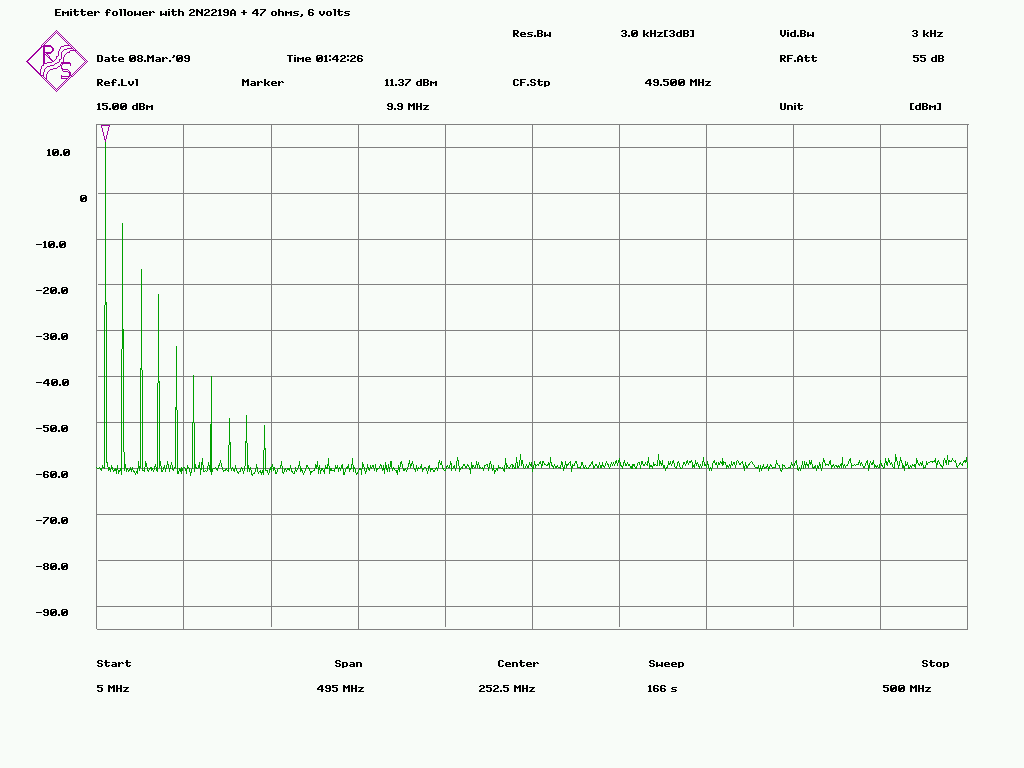
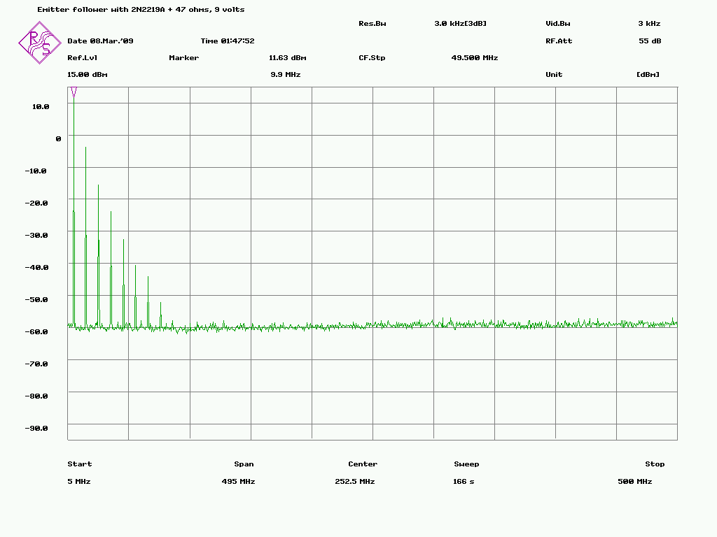
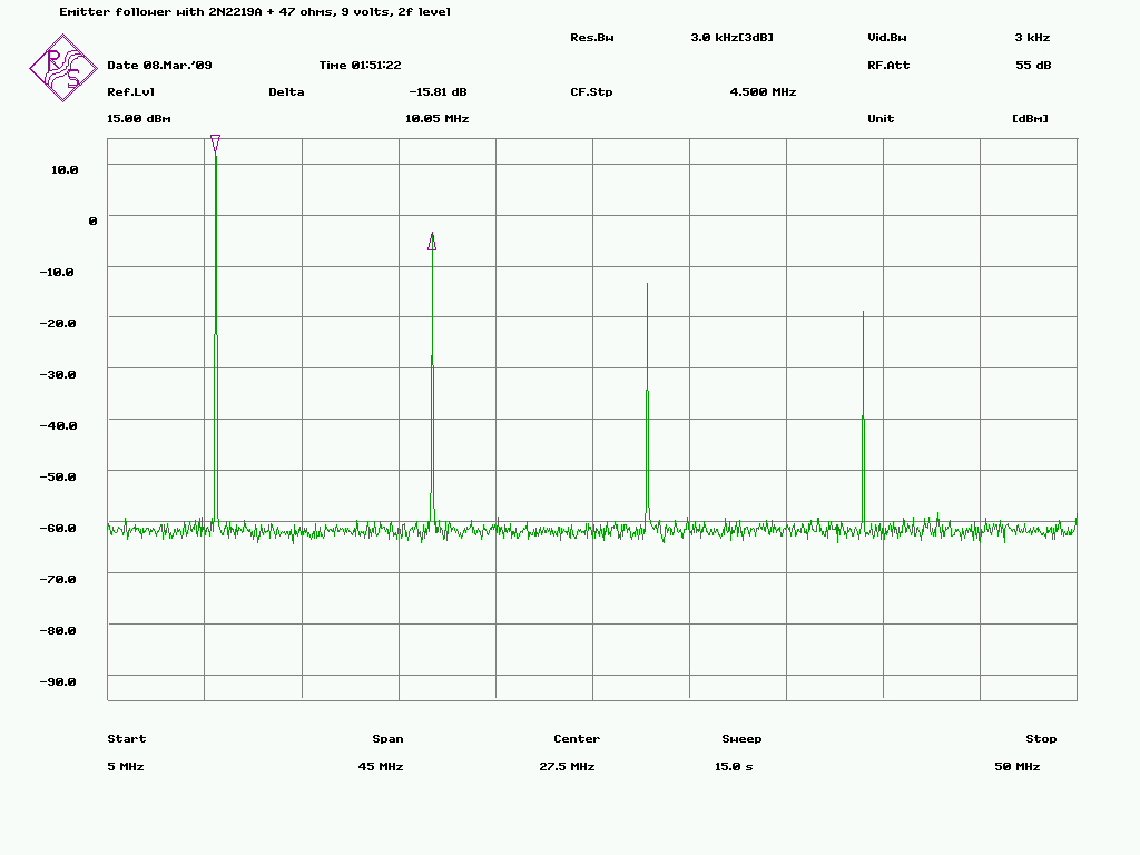
Esa Heikkinen wrote:
>  > Its probably better to increase the emitter current to 40mA or
>  > so and place 47 ohms between the emitter and the output coupling
>  > capacitor a and accept the resultant +7dBm output.
>  > The transistor dissipation will increase and it may be better to
>  > substitute something like a 2N5943, 2N3866, 2N 5109, BFW16A
>  > or similar.
>
> I don't have those 2N types but after some digging found 2N2219A.
> Changed that and 47 ohms from emitter to the ground. I run it first with
> 6 volts, then with 9 volts and then with 12 volts but have to stop with
> uncomplete sweep because it become very hot.
>
> Increasing the current does help with amplifier linearity but not so
> much. However the spectrum looks little bit better now but it's still
> out of spec:
>
> http://www.amigazone.fi/files/gpsdo/544-7.png
> http://www.amigazone.fi/files/gpsdo/544-8.png
> http://www.amigazone.fi/files/gpsdo/544-9.png
>
>
>> About the only way to achieve the distortion you observe is if the
>> capacitance of the wire connecting your emitter follower to the 10544A
>> output is too large (around 50pF or more).
>>
>
> It's about 30 cm. long microwave coax taken out from some RF stuff
> (maybe old cellphone). It's measured capacitance (at the other end free)
> is 36,2 pF.
>
> I'll send the picture later if still needed..
>
>
Esa
A quick and dirty fix is to use a low Q (use a resistor in series)
inductor connected between the cable output and ground (or equivalent
location) of the right value to cancel most of the input capacitance at
10MHz.

Bruce

_______________________________________________
time-nuts mailing list -- [email protected]
To unsubscribe, go to https://www.febo.com/cgi-bin/mailman/listinfo/time-nuts
and follow the instructions there.