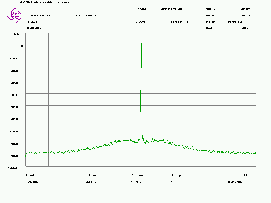
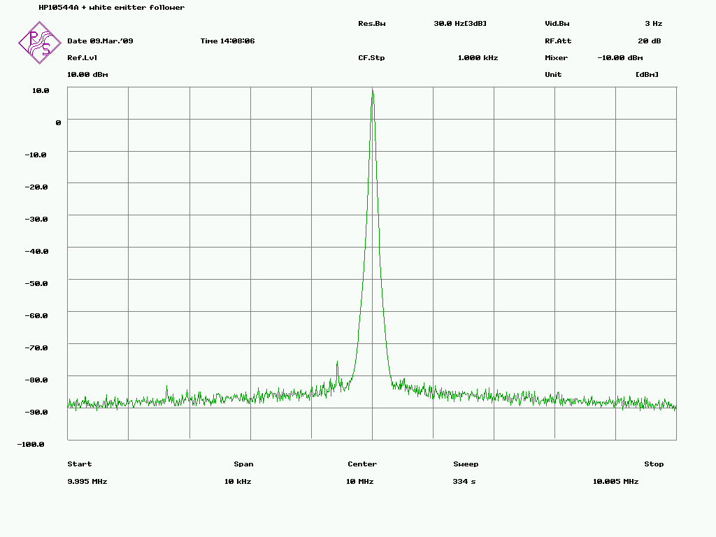
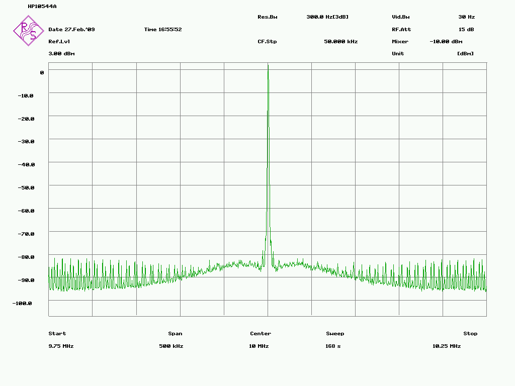
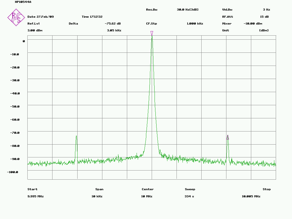
Bruce Griffiths wrote:
> Esa Heikkinen wrote:
>
>>> Since retrofitting an improved oscillator circuit isn't really an option
>>> you will need to filter the output to reduce the harmonic content.
>>> Try a bandpass filter driven by the buffer and terminated in 50 ohms.
>>>
>>>
>> Well I have to decide what to do, get another oscillator or try the
>> filtering. The difference to another oscillators (like tbolt ocxo or
>> LPRO) is so huge that I do not know how hard it would filter the 10544A
>> to the same level, which parts to use and how much it will cost.
>>
>>
>>
>>> Should you retrofit an improved oscillator circuit you may as well
>>> replace the oven controller to eliminate the oven switching frequency
>>> related sidebands.
>>>
>>>
>> Infact the switcher sidebands are now gone:
>> http://www.amigazone.fi/files/gpsdo/544-13.png
>> http://www.amigazone.fi/files/gpsdo/544-14.png
>>
>> It was like thios earlier:
>> http://www.amigazone.fi/files/gpsdo/544-1.PNG
>> http://www.amigazone.fi/files/gpsdo/544-2.PNG
>>
>> It was easier than I expected... When I took the output directly from
>> OSC pins without using the coax connector like you suggested the
>> switcher peaks was gone!
>>
>> So I had a closer look to the PCB today and noticed that it has only 2
>> layers and the ground net is too thin and goes around PCB totally wrong
>> way so that switcher current seems to flow via the signal flow. It's PCB
>> layout design fault, I think that with correct layout design this could
>> be done even with 2-layer PCB correctly.
>>
>> But this is not a problem of course because I will design my own PCB for
>> the final system anyway, having SMA connectors for 10 MHz and EFC. I'll
>> also create separate power supply for ovens and signalling stages.
>>
>>
>>
> Esa
>
> The switcher sidebands will still be there, they are just buried in the
> spectrum analyser noise floor.
>
> Does the board use the recommended LC filters and regulator for the
> oscillator supply as depicted in Figure 3 on the 10544A data sheet?
>
> Reducing the harmonics by 40 dB shouldn't be too difficult.
> However any amplifier after the filter will need to be carefully
> designed to keep the distortion below -60dBc.
>
> Its better to use a multi section LC filter rather than trying to do it
> with a single LC filter.
> The filter phase stability will be better with a multi section LC filter.
>
> Alternatively you could use a bandpass filter combined with some series
> tuned shunt LC circuits to short out the 2nd and 3rd harmonic components.
>
> The required parts shouldn't be too expensive, however you may need to
> wind your own inductors for the series tuned LC circuits.
> Air core or powdered iron core inductors should be OK as long as you use
> shields between filter sections etc.
>
>
> Bruce
>
> _______________________________________________
> time-nuts mailing list -- [email protected]
> To unsubscribe, go to https://www.febo.com/cgi-bin/mailman/listinfo/time-nuts
> and follow the instructions there.
>
>
Esa
Another option (which I used several decades ago with a 10544A) was to
use a double tuned critically coupled RF transformer driven by a unity
gain buffer with another unity gain amplifier buffering the output
across the secondary tuning capacitor. NB the Q of the primary and
secondary tuned circuits should be the same (need to insert a resistor
in the secondary to set the Q). The inductors were hand wound and
trimmer caps were used for tuning.

Bruce

_______________________________________________
time-nuts mailing list -- [email protected]
To unsubscribe, go to https://www.febo.com/cgi-bin/mailman/listinfo/time-nuts
and follow the instructions there.