As Bill suggests, the best way to achieve any-frequency performance with the
newer FE-56xx devices is to pull out the Rb reference frequency and run an
external DDS off it.
I found that the Rb loop frequency in the one I played with was exactly
60MHz, rather than the 50.255MHz of the older units, although it doesn't
really matter what it is. I run mine with an AD9852 in x4 mode (so the clock
is 240MHz), and so have a range of 0 - 90MHz. The only control software I
have at present is the dreadful parallel port program which came with the AD
development kit, so it is useful only as a signal generator. One day I'll
write it something better.
73,
Murray ZL1BPU
----- Original Message -----
From: <[email protected]>
To: <[email protected]>
Sent: Tuesday, April 09, 2013 4:00 AM
Subject: time-nuts Digest, Vol 105, Issue 22
Send time-nuts mailing list submissions to
[email protected]

To subscribe or unsubscribe via the World Wide Web, visit
https://www.febo.com/cgi-bin/mailman/listinfo/time-nuts
or, via email, send a message with subject or body 'help' to
[email protected]

You can reach the person managing the list at
[email protected]

When replying, please edit your Subject line so it is more specific
than "Re: Contents of time-nuts digest..."


Today's Topics:

  1. Re: Changing FE-5650A frequency? (Don Latham)
  2. Re: Trimble SVeeSix -- was DATUM 9390-52054 Grief again...
     (Brooke Clarke)
  3. Re: Changing FE-5650A frequency? (WB6BNQ)
  4. Re: Lady Heather (Achim Vollhardt)


----------------------------------------------------------------------

Message: 1
Date: Sun, 7 Apr 2013 15:29:46 -0600 (MDT)
From: "Don Latham" <[email protected]>
To: "Discussion of precise time and frequency measurement"
<[email protected]>
Subject: Re: [time-nuts] Changing FE-5650A frequency?
Message-ID:
<[email protected]>
Content-Type: text/plain;charset=iso-8859-1

wow, a little more picking will get you to the dds pinout wrt the 24-bit
programming word...

Alexander Wright
On 07/04/13 15:10, Herbert Poetzl wrote:
The purpose of the polymer foam is isolation to keep a
stable temperature throughout the boards.
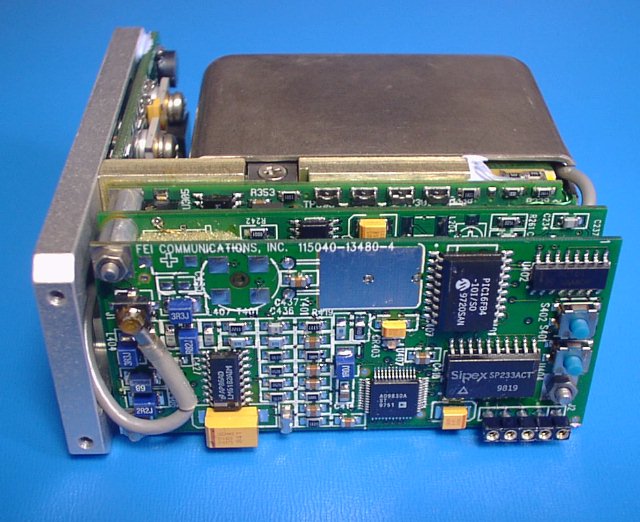
http://www.qsl.net/z/zl1bpu/PROJ/FE5650-2.jpg
The top layer in this image is the DDS board, and it is
basically identical to the FE5680A, which means it can
be adjusted in a wide range, but only does digital synthesis
based on the reference frequency.
But let's see what Bill says to the pictures ... :)
best,
Herbert
Herbert, the board doesn't seem to be the same, the chips which are
visible don't line up with the ones in that picture. Anyway my curiosity
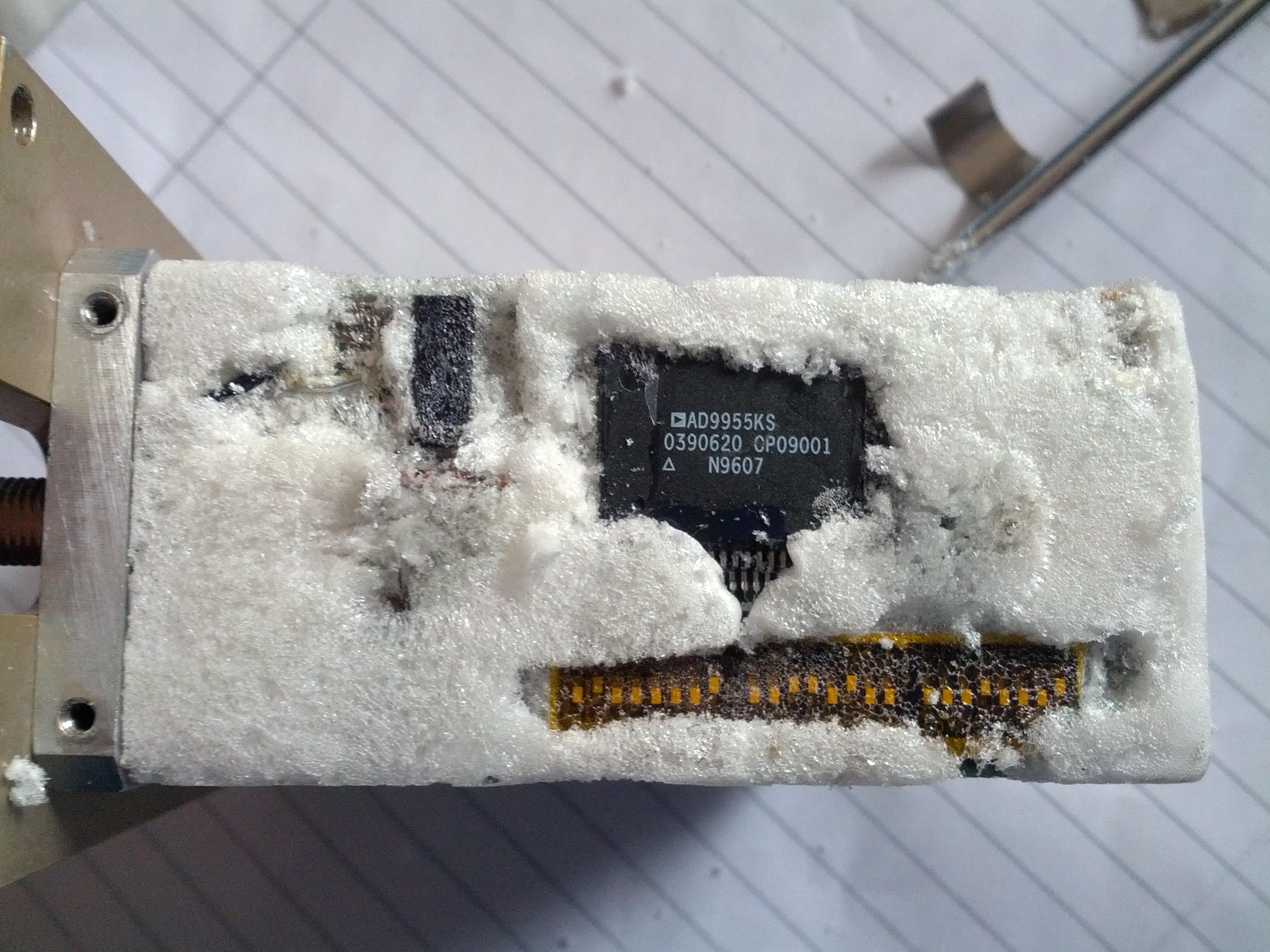
got the better of me and I dug through the foam some more to find a long
row of DIP switches. I bet i can change the divider ratio with some
combination of those:
http://m0tei.co.uk/fe5650pics/IMG_20130407_170929.jpg
Also, you can see that the chip is an AD9955 DDS chip:
http://novatech-instr.com/PDF_files/AD9955.pdf
-
Alec
_______________________________________________
time-nuts mailing list -- [email protected]
To unsubscribe, go to
https://www.febo.com/cgi-bin/mailman/listinfo/time-nuts
and follow the instructions there.
--
"Neither the voice of authority nor the weight of reason and argument
are as significant as experiment, for thence comes quiet to the mind."
De Erroribus Medicorum, R. Bacon, 13th century.
"If you don't know what it is, don't poke it."
Ghost in the Shell


Dr. Don Latham AJ7LL
Six Mile Systems LLP
17850 Six Mile Road
POB 134
Huson, MT, 59846
VOX 406-626-4304
www.lightningforensics.com
www.sixmilesystems.com


------------------------------

Message: 2
Date: Sun, 07 Apr 2013 15:21:58 -0700
From: Brooke Clarke <[email protected]>
To: Discussion of precise time and frequency measurement
<[email protected]>
Subject: Re: [time-nuts] Trimble SVeeSix -- was DATUM 9390-52054 Grief
again...
Message-ID: <[email protected]>
Content-Type: text/plain; charset=ISO-8859-1; format=flowed

Hi:

I spent a lot of time with the SV6 learning about GPS.
http://www.prc68.com/I/Trimpack.shtml#SV6
Note: The Trimpack web page has a bunch of Trimble GPS receivers, not
just Trimpacks.
Have Fun,

Brooke Clarke
http://www.PRC68.com
http://www.end2partygovernment.com/2012Issues.html


------------------------------

Message: 3
Date: Sun, 07 Apr 2013 13:55:13 -0700
From: WB6BNQ <[email protected]>
To: Discussion of precise time and frequency measurement
<[email protected]>
Subject: Re: [time-nuts] Changing FE-5650A frequency?
Message-ID: <[email protected]>
Content-Type: text/plain; charset=us-ascii

Hi Alec,
I am going to agree with Robert (G8RPI) on his assessment, particularly as
the dip switches are clearly visible in one of the pictures. Although I
wonder why Robert feels unfortunate about the [ two chip DDS arrangement ]
?
It matters not the number of chips that make up the DDS. Why ? Because
the actual physics package and its electronics has nothing to do with the
DDS in the older designs. That is, the signal output of the physics
package is a fixed frequency (around 50.255 MHz) that you could capture
and feed to a more modern DDS if necessary as replacement of the old one
is probably not going to happen. However, if it is working then once you
get to a frequency you need you probably not touch it again. So no loss
there.
As for calibration, there is a hole on one side of the can that has a
multi-turn pot that adjusts the "C-field" current. The C-field is a very
fine frequency adjustment. You first adjust the C-field pot to its lowest
setting (as in frequency), then set the DDS to the closest frequency on
downside of where you want to go and then adjust the C-field pot to come
up on to the frequency. The C-field pot is a really fine adjustment, so
we are talking very small movement that will require patience, a better
reference and at least a
oscilloscope to watch the drift rate over a very long time. A truly time
consuming experience.
However, if you leave that C-field pot alone, you will most probably be
inside 1 part in 10 to the minus 9th.
The most recent designs have the DDS in the control loop for the physics
package. In the new internal design in order to change frequencies you
need to actually change the BASE crystal frequency, the DDS and the
firmware to get a new output frequency. So basically a real pain in the
ass.
As for the foam that is sandwiched in between the boards, I agree with
Robert that it is for temperature stability in varying environments. If
the unit is kept in a normal room all the time then the foam is not a
concern and could be carefully cleaned off. There is some other
components that have white stuff that looks more like an RTV type
substance used to hold down a component like what is seen in photograph
IMG_20130407_102937.jpg at the two toroids, That I would leave alone.
Your finding the 12+ MHz just confirms that the design is very similar to
that described in the FTP file I provided. Make sure you record the
switch settings before you change them so you can return to a reference
point.
Although you did not indicate, I assume you downloaded the FTP file ?
Please let me know so i can reduce the storage level as it is not my site
although I have use of it on a short term basis.
Thank you,

Bill....WB6BNQ

Alexander Wright wrote:
On 07/04/13 17:56, Robert Atkinson wrote:
> Hi Alex,
> These units were used as timing references for secure communication
> systems (Havequick). see ebay item 130832014630. Unfortunatly they are
> an older design with a two chip DDS. The other problem is that the "M"
> designation is for military and means they have been partially
> encapsulated with polyurethene foam. You can cut it away but it is very
> easy to damage the PCB. Frequency setting is by DIP switches (under the
> foam) allowing full range of frequency selection. However the output
> filter is narrow so you can't go far from 800kHz.
> Did you buy all seven?
>
> Robert G8RPI.
>
>
Robert,
Thanks for the info! I bought one of these wondering what they were,
took it apart and found the rubidium clock and figured it must be worth
something (more than the 15 quid he was asking) so I bought the remaining
6!
I've taken the foam off the top PCB and i've found that there's a
12.8MHz signal being produced which is then being divided down with an
800kHz logic chip. I should imagine the filter must be on the circuit
board below? I might try changing the frequency
of the DDS chip, removing the frequency divider and tinkering with the
output filter. Do you have any info on what sort of filter I should
expect to find?

Thanks,
Alec M0TEI
_______________________________________________
time-nuts mailing list -- [email protected]
To unsubscribe, go to
https://www.febo.com/cgi-bin/mailman/listinfo/time-nuts
and follow the instructions there.
------------------------------

Message: 4
Date: Mon, 08 Apr 2013 15:54:22 +0200
From: Achim Vollhardt <[email protected]>
To: [email protected]
Subject: Re: [time-nuts] Lady Heather
Message-ID: <[email protected]>
Content-Type: text/plain; charset=ISO-8859-1; format=flowed

Hi Mike,
try typing:

s: Survey
a: Antenna
s: Signal


in that sequence from main menu.

73s Achim, DH2VA


------------------------------

_______________________________________________
time-nuts mailing list
[email protected]
https://www.febo.com/cgi-bin/mailman/listinfo/time-nuts

End of time-nuts Digest, Vol 105, Issue 22
******************************************
_______________________________________________
time-nuts mailing list -- [email protected]
To unsubscribe, go to https://www.febo.com/cgi-bin/mailman/listinfo/time-nuts
and follow the instructions there.