Hi Scott,
I reviewed the material at the N5TNL site and it leaves me wondering.
There are at least three different and separate temperature controlling
areas inside the FEI-5680. One of which has cannot be messed with due
to the fact that it is inherent in its design. That would be the
posistor (i.e., a PTC resistor) that is attached to the 60 MHz crystal
that acts as a general heater.
The other two locations are on the physics package itself. One for the
lamp area and the other is for the cavity chamber. SO.........
The lamp area, I surmise is rather simple as it does not require tight
temperature control like the cavity chamber area would need. The lamp
area just needs a temperature to change and maintain the Rb into a gas form.
The cavity chamber area is way more sensitive to temperature as it
affects the pressure, frequency and stability of the Rb in the cavity.
I suspect that the control mechanism for this area to be more complicated.
The block diagram, while pretty general in nature, does show that the
system (i.e., internal computer) has an A/D monitoring 4 inputs. Three
of the A/D channels are observing "system data" and the fourth is
temperature. What it does not tell us is what temperature or system
data it is monitoring.
SO....... Here is the rub, the only temperature that is truly critical
is the cavity temperature. BUT, the system computer does not really
control that temperature, except possibly monitor it, as indicated on
the block diagram.
Thus the real question is, is that the temperature being referred to in
the monitoring process ? In other words have you traced out the
connections to see what is driving the pin you think is the temperature
input ?
   I would think that the temperature reading would have a steadily
   climbing curve from the application of power to some steady state
   (relative) value.  However, the curve that you selected as
   temperature seems to rise and become steady (relative) some period
   of time after application of power and seems associated with the
   unit going into a lock condition.  OR, so you indicate on some of
   your graphs.
The next big question is have you monitored the frequency and its
stability, externally, to observe what effects are taking place when you
disable this input to the A/D ?
I realize Bert is trying to take FEI to a tighter level, but I wonder if
it would be better to add thermal mass to buffer external ambient
changes rather than screw with the internal control mechanisms.
Particularly seeing as how we have no knowledge of the what the internal
firmware is doing. By thermal mass I mean on all sides of the unit.
The only way to really achieve that would be make a stirred oil bath
container with the FEI suspended in the center of said bath.
That sounds complicated and messy but may be easier than it appears. An
appropriate container would be:
http://www.worldkitchen.com/en/snapware-food-storage/1098437.html
It is made out of polypropylene and can handle at least 130 degrees "C"
and it holds just under two and half gallons of oil. Light mineral oil
runs around $15 a gallon, so two gallons would be the right amount
leaving a little room at the top. Wicking is a problem with wires and
cables but using connectors attached to the lid solves that problem by
breaking the wicking surface. The final question is how much, if any,
external oil cooling would be necessary. That would have to be
experimentally determined. The mineral oil, by the way, has a higher
flash point then the container and is electrically NON-conductive.
Food for thought,

Bill....WB6BNQ


Scott Newell wrote:
Bert asked me to send an update on the FE-5680 tempco mod progress.
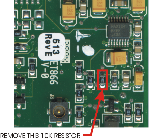
It appears that the FE-5680A temperature signal (or maybe it's really
a current sense signal?) can be disabled by removing a single 10k 0805
surface mount resistor.
Using Elio Corbolante's terrific high-res scans, I've noted the
resistor location: http://www.n5tnl.com/time/fe-5680a/lobotomy.png
Why would you want to disable temperature compensation? As we've seen,
the unit's firmware will adjust the DDS frequency as the temperature
signal changes. If you're using the '5680 inside a control loop, it's
likely to conflict. By removing the resistor, that channel of the 12
bit ADC will be tied to ground through an existing 2.21k resistor. The
unit will see a constant 0 counts from the ADC and assume it's really
cold.
I modified one unit and monitored it for a few hours over a range of
temps, running it nice and hot with no heatsink, then blasting it with
a fan and placing it on an ice-cold heatsink. I observed no change in
the DDS tuning words.
It's a really easy mod--remove four screws, set aside the insulator
sheet, and apply your hot leucotome/soldering iron.
I've also found a simple mod to replace the temperature signal with
the output of the unused trimpot. This allows you to simulate any
temperature you want. If there's any interest, I'll set up a test and
monitor the DDS tuning words as the unit's firmware tries to adjust to
the fake temp signal.
_______________________________________________
time-nuts mailing list -- time-nuts@febo.com
To unsubscribe, go to https://www.febo.com/cgi-bin/mailman/listinfo/time-nuts
and follow the instructions there.