Transformer isolation isn't helping much at RF, as you will capacitively
couple through the transformer. I've been bitten by that in real life,
as I was called in to solve issues in someone elses design. It was only
when I introduced an RF choke that we got conducted noise battled. It's
also not enough, as the RF choke needs an RF path to ground in order to
start rejecting effectively, which was the issue another time, so you
want an RF choke with caps to ground on the inside.
The galvanic isolation can be done using transformer or capacitors after
that.
There is an over believe in isolation, as it only takes one mistake to
break the system. Another approach is to ground everything, cross-ground
etc. and bring the DC/power-spurs down through conduction. It have
proven itself easier to ensure RF properties when shield and chassi is
tied hard to each other, as it provides good RF conduction and the cable
does not act like an antenna against the shield for the RF power being
unbalanced. The RF choke then acts to separate the chassi RF from that
of the board, assisting in the balance.
Transformers can provide RF shielding, if they have double shields
between the coils, and where the shield of each side is connected to
it's ground. That way each coil will capacitively terminate in it's own
shield, and the remaining capacitive coupling will mainly be between the
shields and hence grounds. I rarely see people doing this.
I've been bitten multiple times by the capacitive coupling in
transformers, and only when I found a way to handle it things have
started to work. It's not all magnetics.
Cheers,
Magnus

On 12/19/2015 12:33 AM, Tim Shoppa wrote:
All the inputs and outputs were deliberately transformer isolated. Why
break the isolation by using capacitor from coax shield to chassis ground?

I do realize that some isolation transformers have "extra floating turns"
to give transformer action that cancels stray capacitive coupling. I don't
think the capacitors tying coax shield to chassis ground can serve that
purpose.

Tim N3QE

On Mon, Nov 30, 2015 at 3:02 PM, Anders Wallin <anders.e.e.wal...@gmail.com>
wrote:
HI all,
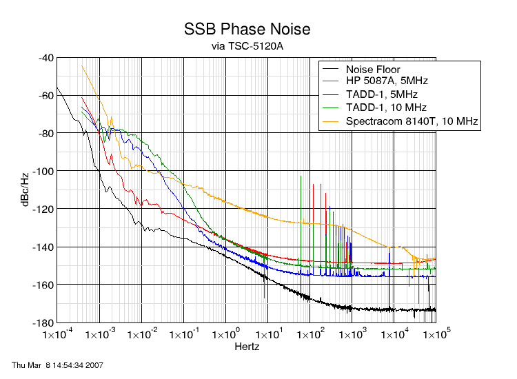
I need to build a few distribution amplifiers (>90% for 10MHz, sometimes
maybe 5MHz) and instead of reinventing the wheel I decided to try to
modernize the TADD-1 into an all (almost) SMD design. Here are some draft
sketches:
http://www.anderswallin.net/2015/11/frequency-distribution-amplifier-plans-a-k-a-smd-tadd-1/
Does this sound/look reasonable or crazy?
Any suggestions for op-amps to try and/or compare to the AD8055?
What causes the extra phase-noise below 1 Hz offset in John A's result:
https://www.febo.com/pages/amplifier_phase_noise/amplifier_phase_noise.png
Suggestions for a low noise DC-regulator circuit? The 12-24VDC supplied to
this board will most likely come from a switched-mode PSU, so filtering of
common-mode noise is mandatory.
I found the TI LP38798 shown in the schematic by googling - if someone has
a proven a measured design that would be a safer choice. In any case more
filtering (e.g. ferriites) is probably a good idea.
This design will be available on my blog or on github when it is done - if
anyone is interested.
Thanks,
Anders
_______________________________________________
time-nuts mailing list -- time-nuts@febo.com
To unsubscribe, go to
https://www.febo.com/cgi-bin/mailman/listinfo/time-nuts
and follow the instructions there.
_______________________________________________
time-nuts mailing list -- time-nuts@febo.com
To unsubscribe, go to https://www.febo.com/cgi-bin/mailman/listinfo/time-nuts
and follow the instructions there.
_______________________________________________
time-nuts mailing list -- time-nuts@febo.com
To unsubscribe, go to https://www.febo.com/cgi-bin/mailman/listinfo/time-nuts
and follow the instructions there.