Dear colleagues,
as you may remember I am still working on my own GPSDO project.
So far I have populated all the components on the PCBs I made, and I have
written some very basic software to test everything. Currently, I am
running following simple test:
I set my DAC to a constant value (5 Volts at the EFC input of the OCXO),
and then I send the phase measurement to the PC via RS-232 where I can log
it. More on that later.
Here is my schematic (not much has changed since last time):
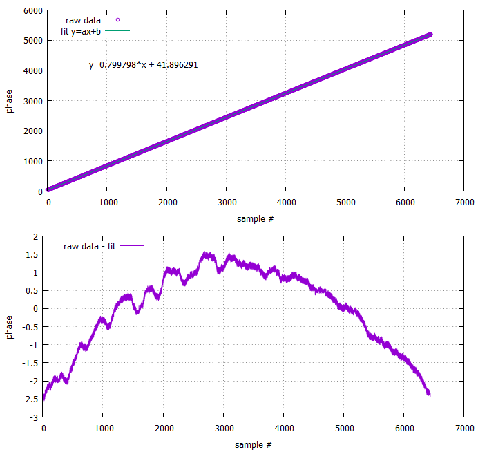
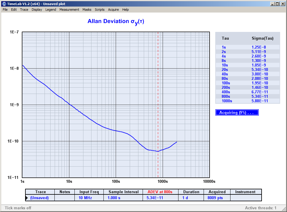
https://hb9fsx.ch/files/gpsdo/gpsdo_schematic.pdf

The GPS phase detection happens on page 3. I use the TDC7200 as
interpolator.
Inside the STM32 microcontroller, I let a timer run with the 10MHz clock.
The timer overflows to 0 when it reaches the value 9999999.
Further, the 1PPS pulse from my GPS module triggers the interpolator, and
is delayed by max. 2 clock cycles. The delayed signal stops the
interpolator and is used as a capture event of the timer.
So, when the OCXO has the right frequency, the captured value would always
be the same. To determine the phase, I use the following code:

if(captured value >= 5000000)
    phase = 10000000 - captured value;
else
    phase = -captured value;

with the aid of this bit of code, my phase value is always perfectly in the
interval -5000000 to +5000000. My test today was to let the OCXO run with a
fixed voltage at its EFC input, while I recorded the resulting phase data.
My recorded data is here:

https://hb9fsx.ch/files/gpsdo/phase.txt

Now I made two plots (here: https://hb9fsx.ch/files/gpsdo/phase.png). The
upper is the raw phase data, and I also fitted a linear function to it
(i.e. if the OCXO has a constant frequency but has some offset from 10 MHz,
the phase would drift linear into one direction - at least I expect it to
do so).
The lower plot is what results when I subtract my linear fitted function
from the measured phase. I am wondering whether this makes some sense? One
can see some wiggles and ripple, especially between sampel 0 and 3000. Is
this the GPS jitter I see there?
Further, I also imported this phase data into Timelab and determined the
ADEV. Here is my plot:

https://hb9fsx.ch/files/gpsdo/timelab.png

This trace is kind of what I expect, but since I use a OSA/UCT 8663 double
oven OCXO, I would have expected it to be much lower. Something in the
1e-12 regime perhaps? is that realistic? As one can see at tau=800s, the
ADEV is around 5e-11, so is this really all I can expect from this very
sophisticated OCXO? (However I should maybe add that the OCXO is brand-new
and has never been used before, so maybe it has some initial aging?).
I have no plots about the temperature, but this is quite constant.
For the GPS module, I used an active outdoor antenna at the window ledge.
Not optimal, but better than an indoor desktop antenna, I guess.

Is this some plausible data I have here, or do I measure complete crap?

It would also be great if someone would look at my code. Maybe I am doing
something wrong when I read out the TDC7200?
The code is here https://hb9fsx.ch/files/gpsdo/code/  and the most
important function is perhaps get_tic().

I am looking forward to any good hints on this! :-)
best
Tobias
HB9FSX
_______________________________________________
time-nuts mailing list -- time-nuts@lists.febo.com
To unsubscribe, go to
http://lists.febo.com/mailman/listinfo/time-nuts_lists.febo.com
and follow the instructions there.