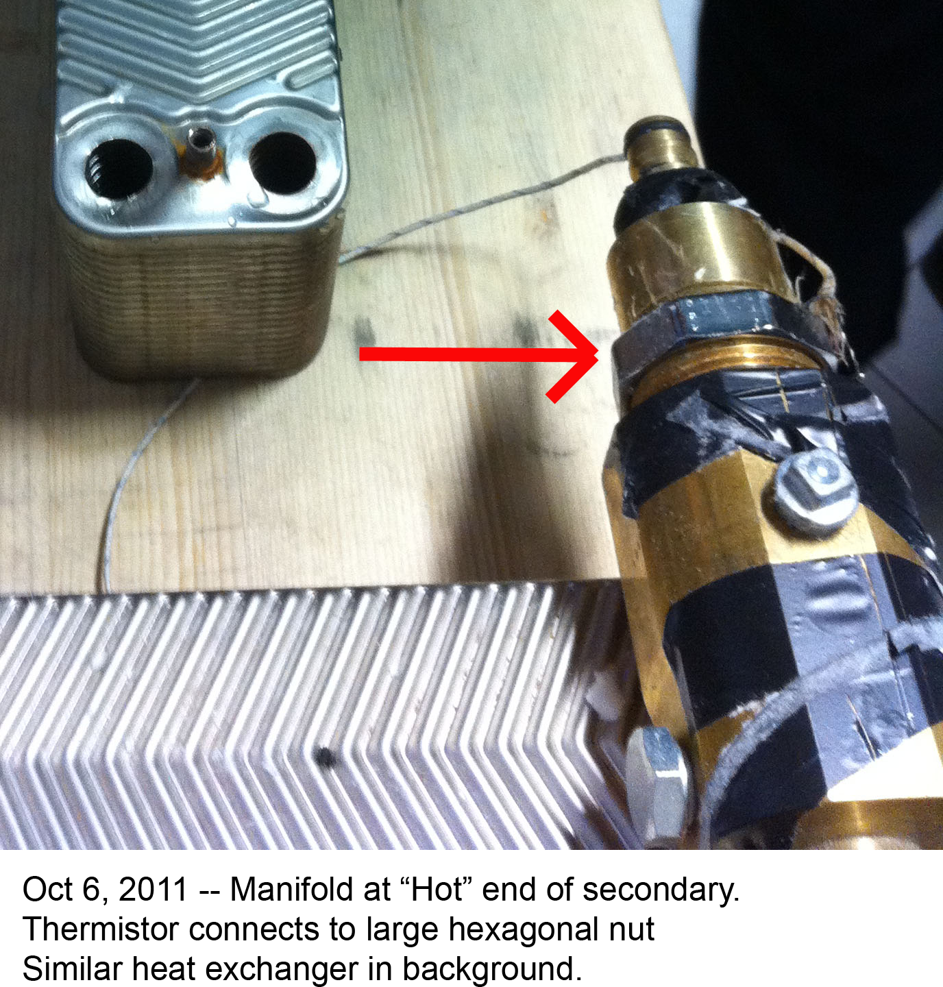
A question that seems to need answering is: Why is the black electrical tape
wound around the manifold at the location where the thermocouple would possibly
hit if pushed downward by the insulation?  Is there some purpose for tape in
this particular location?http://lenr.qumbu.com/lenr_spicepics/111010_1C_crop.png
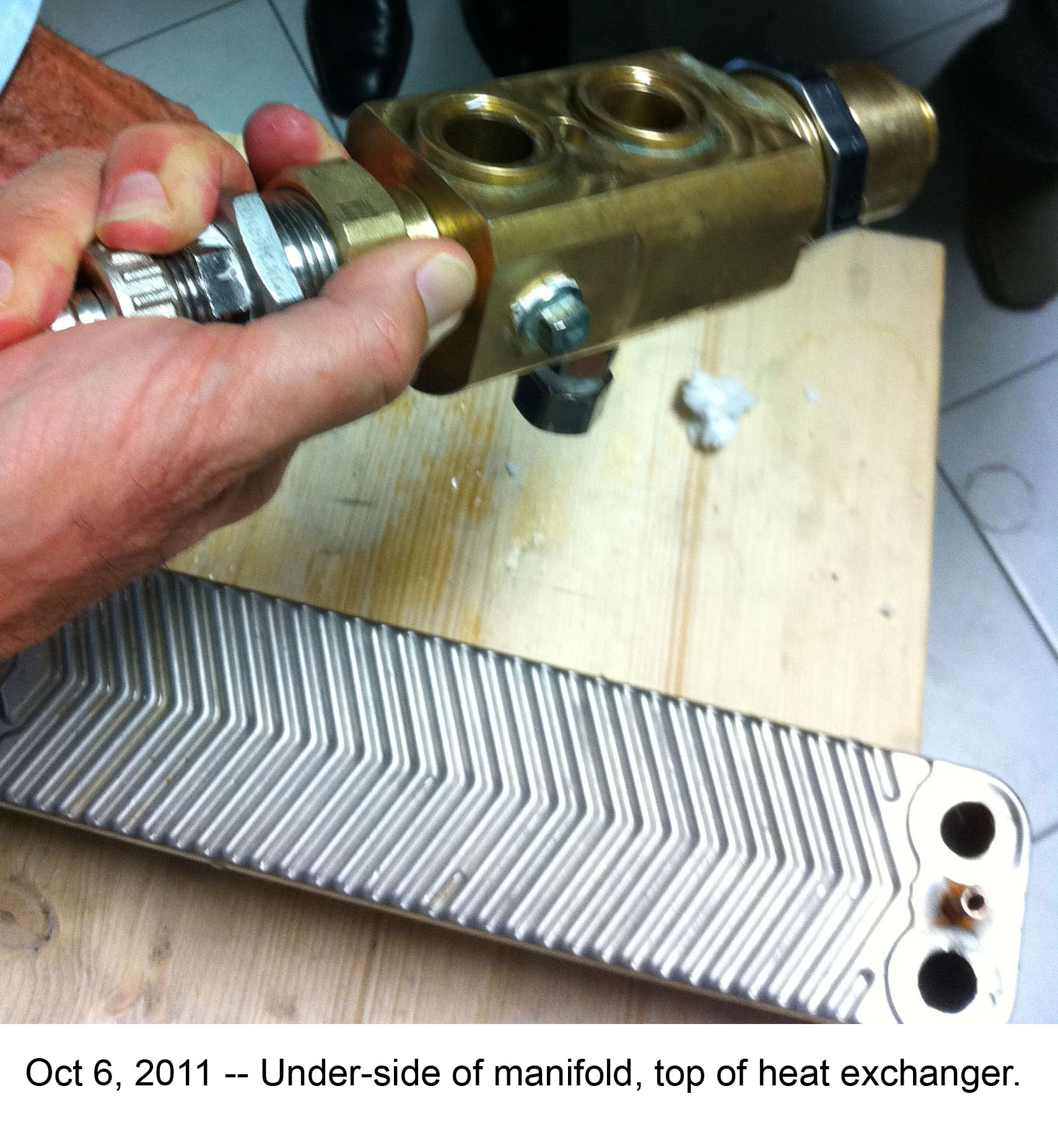
It sure looks like an attempt to keep the TC from contacting the metal of the
manifold.

Dave


-----Original Message-----
From: Horace Heffner <hheff...@mtaonline.net>
To: vortex-l <vortex-l@eskimo.com>
Sent: Fri, Dec 9, 2011 4:11 pm
Subject: Re: [Vo]:Tests with thermoelements and tape.


n Dec 9, 2011, at 9:40 AM, Jed Rothwell wrote:
> Horace Heffner <hheff...@mtaonline.net> wrote:

 The air gap the thermocouple extends out into is large.  It is a
 gap that is longitudinally between the nut and the manifold, and
 radially between the nut outer surface . . .

 I do not think so. The insulating material is flexible and fits
 tightly. Also, the TC is against the flat surface of the nut,
I don't think so.  The wire is against the nut, but it is not clear
he thermocouple tip is.
Here is another view of the thermocouple tip after the insulation was
emoved. You can see it extends out beyond the nut, even though the
ire is bent upwards at the time of the photo.
http://lenr.qumbu.com/lenr_spicepics/111010_1C_crop.png
A cropping with the thermocouple tip circled in red is attached.
Here is photo of manifold with thermocouple removed.  Air space is
robably about 5 mm deep, 2 cm wide?  Also threads prevent firm wide
rea contact.
http://lenr.qumbu.com/lenr_spicepics/111010_2_crop.jpg
Photos are from Alan Fletcher's site, the page with the nifty FEA
imulations:
http://lenr.qumbu.com/rossi_ecat_oct11_spice.php

est regards,
Horace Heffner
ttp://www.mtaonline.net/~hheffner/