On 11/07/2015 01:21, ste...@malikoff.com wrote:
I've adjusted the drawing based upon some of the measurements
provided, so far.
I'd like to get it as accurate as possible. So, I've taken some of
Adam's photos and annotated them with labelled arrows (hope that's ok
Adam). Would it be possible to get these? Hopefully this will clarify
things. One or two labels are repeated, I know:
http://www.surfacezero.com/g503/data/500/dimension_check-IMG_3161.jpg
"flush with bottom edge?": yes, it is.

b = 93.5mm at the position shown, but it's slightly tapered,
      presumably for purposes of injection moulding.  If you measure
      it just above the flange (the part with thickness "i" in that
      photo) it's 94.5mm.  I'd not noticed that before.
d = 56.95mm
g = 4.93mm - 4.98mm depending on exactly where/how I measure it
h = 106mm
i = 2.46mm
j = 33.18mm
k = 11.67mm
L = 2.7mm where you drew the line, tapering to 2.3mm at the rear
      edge (for injection moulding again)
m = 14.25mm
http://www.surfacezero.com/g503/data/500/dimension_check-IMG_3162.jpg
q = 15.5mm
r = 6.35mm (it's a 1/4" hole to clear a 10-32UNF machine screw,
      which screws into a Tinnerman nut on the top crossmember of
      the rack)
s = 11.1mm (hard to be absolutely accurate with the tools I have,
      but that is suspiciously close to 7/16")
t = 27.9mm where you've drawn it.  You obviously realise it goes
      in further under the flange, radiused as shown in IMG_3144.
u = 11.27mm
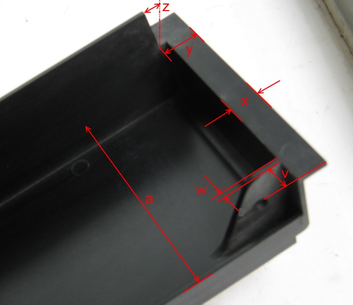
http://www.surfacezero.com/g503/data/500/dimension_check-IMG_3144.jpg
a = 91.05mm (that's from upper surface to upper surface)
v = 9.21mm (average of two corners)
w = 2.53mm (this tapers as well, to 3.1mm at the base)
x = 12.25mm
y = 15.5mm (but on mine, the piece of the flange that y is the width
       of, is almost 1mm wider on one side, but only in the part
       hidden by the flange that Z points to)
z = about 0.5mm - you're trying to measure the taper on the edge of
       the flange?  Not easy to be accurate.
That flat part, across which you're measuring "x" and "y", looks as if
it goes all the way across the bottom in IMG_3161 (where you've measured
"k") but it doesn't on mine. It only goes as far as you can see in
IMG_3144, and there are machining marks in the plastic where the rest
has been cut away - and from the look of the marks, they're in the mould.
 Noel: thanks for trying the drill bits on the radius. From the
original TU10 photo I determined 9.6mm, Pete says 9.5mm so I'm not
too far out. I have adjusted it to 9.5mm anyway, along with most of
the other measurements provided.
Bear in mind that as this was designed in the US, the design
measurements and tools were almost certainly imperial rather than
metric. So that radius was probably cut on the master with a 3/4"
cutter, rather than 19mm. That makes the radius 3/8", which is 9.525mm:
slightly larger than 9.50mm but closer to 9.5 than to 9.6. Though I
doubt anyone cares much about 0.1mm here, let alone 0.025mm :-)
--
Pete

Pete Turnbull