Peter Stuge wrote:
Juhana Helovuo wrote:
Here are some images of my first (incomplete) prototype:
http://alpskari.asiantuntijat.org/~juhe/spi-flasher-piirilevyt/
Looks like a great start!
Now there is more progress. After some building, coding, and debugging I
have the tester sort-of-working.
The first version of the hardware works.
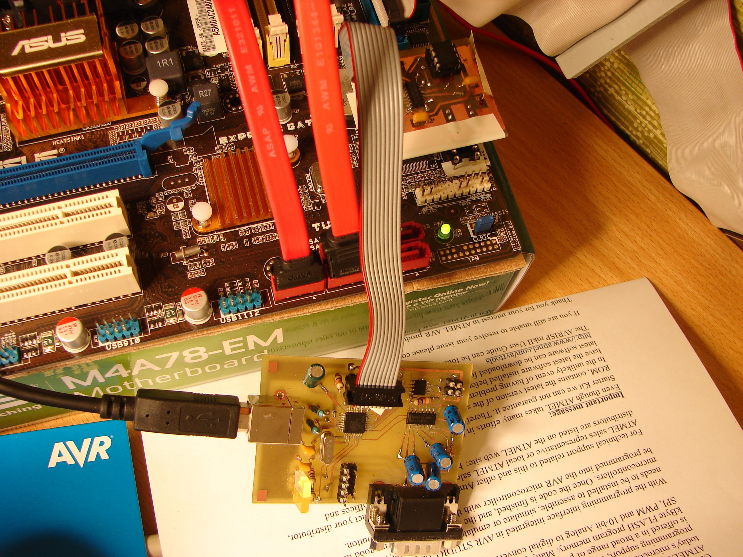
In this image you can see the tester plugged into an Asus mainboard:
http://alpskari.asiantuntijat.org/~juhe/in-system-flasher/DSC08430.jpg
Today I successfully used this setup to reflash the mainboard from the
host PC via flashrom.
The USB cable goes to a host computer, which is running a modified
flashrom program. The flashrom is extended with a serprog_spi module,
which can transfer SPI over the serprog protocol, and additionally
toggle SPI bus multiplexer between the MCU and mainboard at the
beginning and end of programming.
Target reset switch is still operated manually, but there is hardware
support for operating also that from the tester board. Reset pins on the
mainboard need to be connected to pin header in the corner of the bigger
PCB, and flashrom needs to be extended to send also the reset command to
the tester. The ATX power button can be operated in the same fashion.
The tester hardware has the following features:

* Single USB connection to host PC, tester is USB powered.
* RS-232 serial port to collect boot log from the target mainboard.
Tested to work at 115200 bps.
* Two software-controllable switches for controlling mainboard
pushbutton inputs. Button-sensing voltage on mainboard need not be the
same as Vcc on tester.
* Small PCB mounted to mainboard can be powered by tester PCB or mainboard.
* Mainboard can operate normally even when tester has no power.
* Tester can access the ROM also when disconnected from the target
mainboard.
* Two software-controllable LEDs to impress people.


The work is still quite incomplete:
* The first PCB had two layout errors (corrected by jumper wires), so it
needs some rework.
* Some host-side software is missing. Flashrom extension or a separate
program is needed to control the pushbutton inputs.
* The PCB could be extended to include a software-controlled isolated
switch to control a relay, which can switch mains power of the target
mainboard on or off. I am still uncertain whether I want to have
self-hacked devices with 230 VAC parts in my house.
* Currently there is no tester firmware that could operate both the SPI
and RS-232. The main problem is that the AT90USB162 microcontroller
supports only up to five USB endpoints (including default control EP). I
do not know if it is possible to implement two USB CDC class virtual
serial ports with less than seven EPs. With two serial ports, one could
represent the RS-232 interface, and other be used to control the
programmer without writing any custom USB drivers.
This could be solved either in software by writing a custom USB driver
for both the tester and the host, or in hardware by replacing the
microcontroller with a more capable model. If anyone on the list can
suggest any easier solutions, I'd be glad to hear about them.
* The handling of SPI ROM is horribly slow. Programming and verifying 1
MByte ROM takes about half an hour. The main suspect is nonexistent USB
data buffering in the tester firmware.
Best regards,
Juhana Helovuo

--
coreboot mailing list: coreboot@coreboot.org
http://www.coreboot.org/mailman/listinfo/coreboot