On Thu, 2009-12-10 at 11:22 -0500, Martin Pinkston wrote:
> Good Afternoon listers,
> I have posted a picture of my mini mill.
> The reason I wanted to do a conversion over to EMC was because the Centroid
> OS is very antiquated and when I saw what EMC would do, I knew it would make
> the mini mill more flexible.
> The Centroid OS has a very limited memory to about 250 lines on NC code and
> no buffer.
> And since I have a CAD CAM system updating the OS looked very doable.
> Thanks,
> Martin
I took some time to look at your blog site. The mill looks like it's
fairly well built. I'm not a big fan of round column mill's but I have
never used one and it may have some advantages.

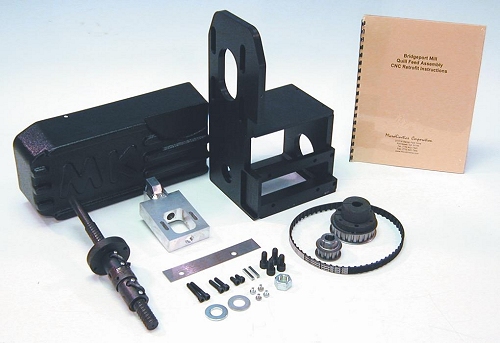
I see the Z axis is driven by the quill rack and pinion, which tend to
have a lot backlash. You might consider, cruising eBay for a short ball
screw (double nut or adjustable preloaded only) and mill up the bits to
drive the quill directly with the screw.
http://www.microkinetics.com/images/quillkit.jpg
http://pico-systems.com/zaxis.html

Considering the results of your other projects this should be a piece of
cake. :)

When you checked the axes for squareness, did you use an indicator and
square clamped to the table or use the table surfaces? It looks to me
that this machine should be pretty square. If the gibbs are worn the
table might rock. A little Prussian blue might indicate something
needing attention.

The top two board pictures look like a dual power supply with PWM
voltage or current control(?). The SG3526's are listed as REGULATING
PULSE WIDTH MODULATOR. These seem to control the nearby power FET's
which push-pull the large inductors just above the FET's, creating a
higher voltage AC. The AC is then converted to DC by the diode array,
just above the inductors. At the top, are capacitors that smooth out any
ripple that the diodes pass on. My guess is that the red and black wires
at the bottom go to a power transformer? The upper red and black wires
go to the motor drivers?

The next board down looks like the CPU/logic board which won't be
needed.

The next board labeled INPUTG on the upper right corner, I'm guessing is
for digital input from limit and home switches? There are four power
switches that may control relays or solenoids.

The last board looks like the, or an, axis motor driver. How many of
these do you have? I bet those red and black wires come from the first
board. The screw terminals on the middle left edge go to the motor or
motors? It looks like there is a microprocessor on this board, so there
may be a proprietary motion command input from the CPU/logic board which
the microprocessor turns into step pulses that goes to the power side of
the board on the left, but then how does your .pdf file fit in? It would
take more employing the little gray cells to figure this out. I may
concede to Jon and recommend using the Gecko's.

--
Kirk Wallace
http://www.wallacecompany.com/machine_shop/
http://www.wallacecompany.com/E45/index.html
California, USA


------------------------------------------------------------------------------
Return on Information:
Google Enterprise Search pays you back
Get the facts.
http://p.sf.net/sfu/google-dev2dev
_______________________________________________
Emc-users mailing list
[email protected]
https://lists.sourceforge.net/lists/listinfo/emc-users