You could delete the volume of the cylinder you’ve created
by means of extrusion and then delete one of the cylinder’s
flat surfaces using the |Delete| command. However, it won’t
give you what you want, because the box “holding the
cylinder” will be unaware of the presence of the cylindrical
hole.
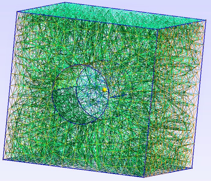
I tried this:
|Plane Surface(1) = {1, 2}; // square minus the circle
out1[] = Extrude {0.0, 76.2, 0.0}{Surface{1};};
Plane Surface(2) = {1};
out2[] = Extrude {0.0, -76.2, 0.0} {Surface{2};};
|
Which results in the 2D mesh you find in the attachment.
Perhaps this is what you’re looking for?
I also tried combining those two volumes using |Compound
Volume(4) = {out1[1], out2[1]};|, but like you, I got
GRegion Compound errors. Probably some basic restriction
from triangulations I’m overlooking. This only means your 3D
meshes will be clearly stopped at a flat interface about
half-way through those two boxes, but you’ll still have a 3D
mesh. I was hoping that the Compound Volume would make some
tetras across this boundary though… But with the above
lines, you’ll have a working mesh.
2014-08-28 17:08 GMT+02:00 Omid Mahabadi
<[email protected]>:
Hi Christophe and Gmsh team,
I've been trying to model a simple cube with a
cylindrical hole that is NOT through-going (i.e., its
depth is smaller than the depth of the cube), as shown
in the attached picture. The Extrude command doesn't
seem to work since it will extrude both surfaces
(exterior and interior -- hole) at the same time. I know
I can define all the surfaces, surface loops, and
volumes manually, but is there a better way of defining
something like this in Gmsh?
I also tried to use the Compound Volume command by first
defining two volumes from Extrude and then trying to
combine them but I'm getting errors for the Compound
Volume visualization (Error: Cannot evaluate bounds on
GRegion Compound) and when I mesh the geometry, the
actual shared interfaces are still existing, although by
the notion of compound from the documentation, the
internal interfaces should be neglected. Here is the
geometry file:
// Characteristic length (==> element size)
cl_external = 25;
cl_excavation = 5;
// External boundaries
Point(1) = {-127, 0.0, -127, cl_external};
Point(2) = {+127, 0.0, -127, cl_external};
Point(3) = {+127, 0.0, +127, cl_external};
Point(4) = {-127, 0.0, +127, cl_external};
Line(1) = {1, 2};
Line(2) = {2, 3};
Line(3) = {3, 4};
Line(4) = {4, 1};
Line Loop(1) = {1, 2, 3, 4};
// Excavation boundaries
Point(5) = {0.0, 0.0, 0.0, cl_excavation};
Point(6) = {19.05, 0.0, 0.0, cl_excavation};
Point(7) = {0.0, 0.0, 19.05, cl_excavation};
Point(8) = {-19.05, 0.0, 0.0, cl_excavation};
Point(9) = {0.0, 0.0, -19.05, cl_excavation};
Circle(5) = {6, 5, 7};
Circle(6) = {7, 5, 8};
Circle(7) = {8, 5, 9};
Circle(8) = {9, 5, 6};
Line Loop(2) = {5, 6, 7, 8};
//Using compound volumes
Plane Surface(1) = {1};
out1[] = Extrude {0.0, 76.2, 0.0}{Surface{1};};
Plane Surface(2) = {1};
out2[] = Extrude {0.0, -76.2, 0.0}{Surface{2};};
Compound Volume(3) = {1, 2};
I also tried to create the geometry in CAD software and
imported it as iges, brep or step formats but for reason
the hole is not there completely. See for instances the
iges file attached.
Can you kindly shed some light here? Am I doing
something wrong? Or are there Gmsh tricks/commands that
I can use to achieve my goal?
Thank you,
Omid
--
Omid Mahabadi, Ph.D.
            Geomechanica, Inc.
            http://www.geomechanica.com/
            Tel :+1-647-478-9767
            Cell:+1-416-824-2408


            _______________________________________________
            gmsh mailing list
            [email protected]
            http://www.geuz.org/mailman/listinfo/gmsh
            <http://www.geuz.org/mailman/listinfo/gmsh>
--
Oliver Willekens
        PhD Student
        LCP group logo <https://lcp.elis.ugent.be/>

        Liquid Crystals & Photonics Group
        Sint- Pietersnieuwstraat 41
        9000 Gent
        Phone: +32 9 264.89.51