Hi,

To enjoy the links, replace CS-tube with CS_tube in the links.
Cheers,
Magnus

On 10/31/2016 09:54 PM, Skip Withrow wrote:
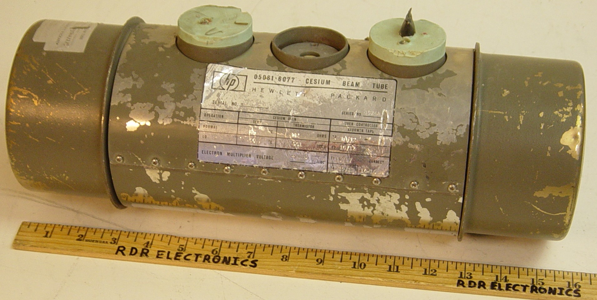
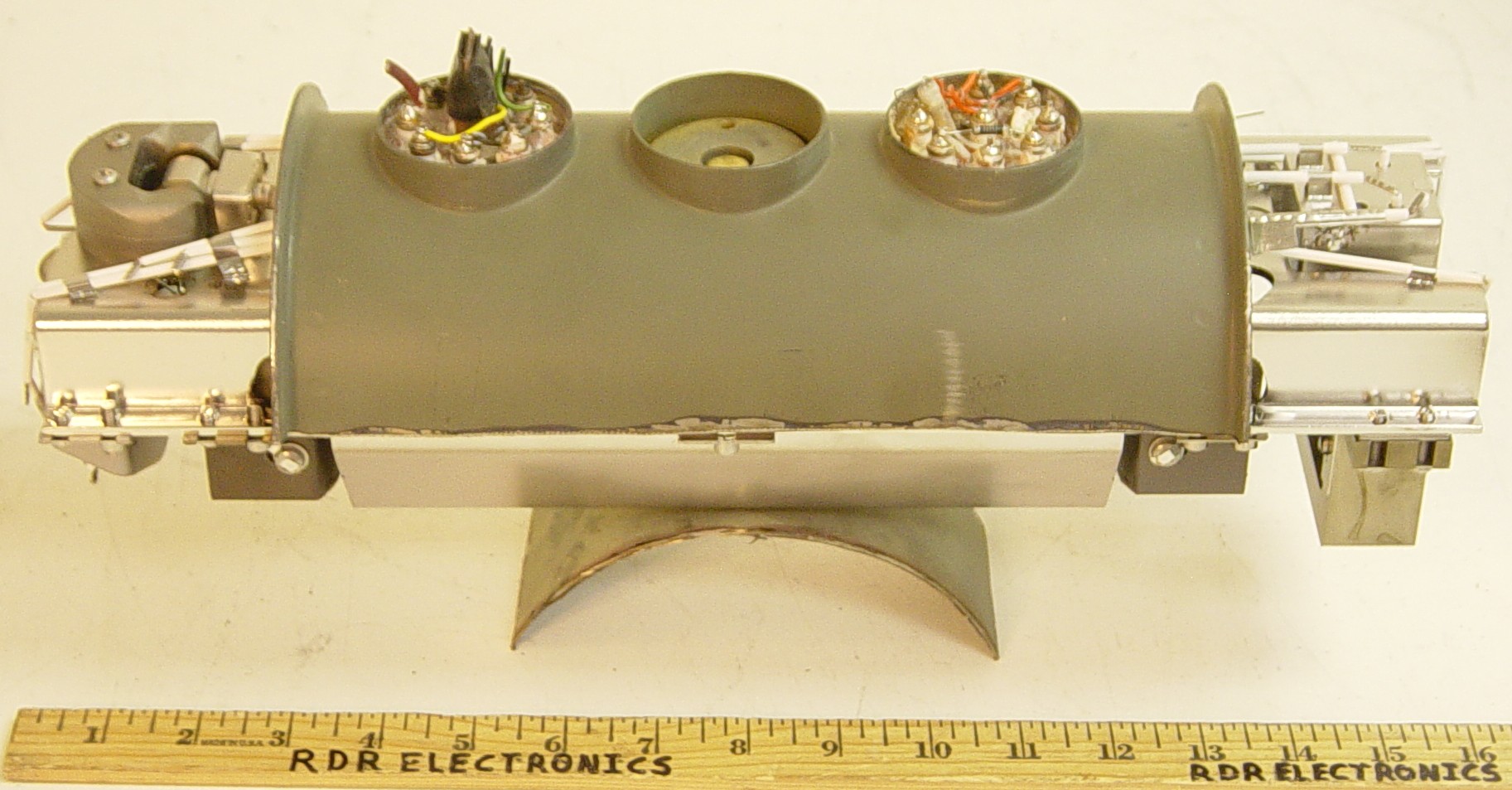
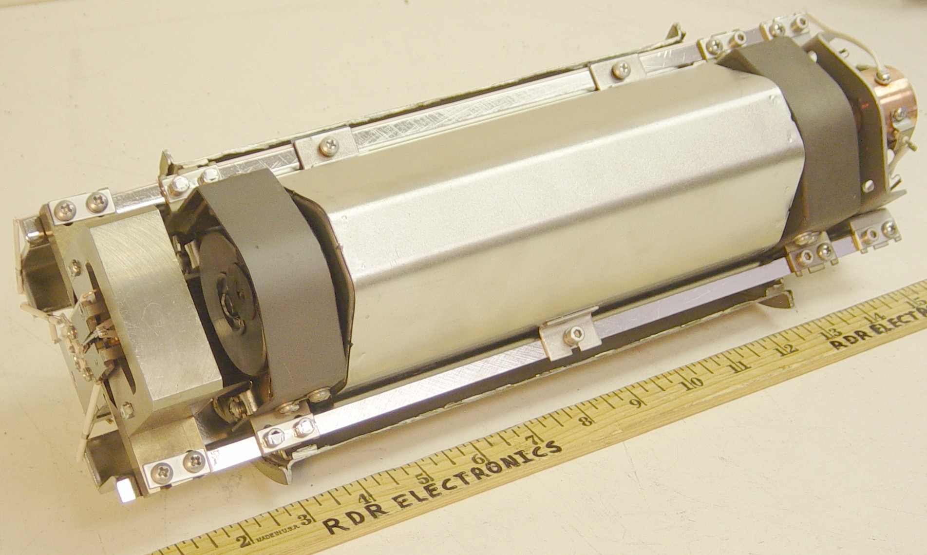
Hello Time-Nuts,


I recently acquired a stock of dead cesium beam tubes, and my curiosity got
the best of me, so I have cut one open.  After watching lots of YouTube
video of burning and exploding cesium I was a little leery at first. The
first step was to make a very small hole just to let a small amount of air
in, no flames or heat so I let it sit for a while for any reactions with
air to take their course.  Next I proceeded to cut off the ends, and after
that the bottom of the unit, finally I trimmed the top off as far as I
could.  Pictures are linked below for your enjoyment.  I have attached two
of the before and after at low resolution.


1. http://www.rdrelectronics.com/skip/CS-tube/cstube1.jpg


This is the before picture of a tube (not the actual one opened).  It is HP
part number 05061-6077.  The band around the center of the tube is a mu
metal shield that is removed by removing the screws along the seam.
Unfortunately
11 of the 14 tubes that I received had the cables cut as shown (ouch!).


2. http://www.rdrelectronics.com/skip/CS-tube/cstube2.jpg


This is a shot of the deconstructed tube.  The cesium oven is on the left,
the microwave cavity is in the center (under a metal cover), and the
detector is on the right.


3. http://www.rdrelectronics.com/skip/CS-tube/cstube3.jpg


This is the oven end of the tube.  The oven (with the cesium) is the copper
vessel.  The ion trap assembly is at the top (with magnet).  The first beam
magnet is between the oven and the microwave cavity.  One thing that I can
say is that HP brought the art of spot welding to a new level.  Note the
stainless steel strips welded over the screw heads (and lots of other
things).


4. http://www.rdrelectronics.com/skip/CS-tube/cstube4.jpg


This is the detector end of the tube.  I believe the hot wire ionizer is
the broken metal strip.  The electron multiplier/detector is in the metal
box above it.  The second beam magnet sits between the microwave cavity and
the electronics at this end of the tube.  I don’t think I broke the
filament, this was probably the failure mode of this tube.  Also note that
all the wiring insulation is ceramic tubing, since insulation that out
gasses in vacuum is a no-no.


5. http://www.rdrelectronics.com/skip/CS-tube/cstube5.jpg


This is the bottom view of the tube for completeness.  I have not yet
removed the cover that is over the microwave cavity (and has the C-field
coil around it).


6. http://www.rdrelectronics.com/skip/CS-tube/cstube6.jpg


This is the top of the tube with the potting compound removed.  I was
surprised to find a couple of embedded resistors.  I guess the good news is
that it would be easy enough to remove the potting and solder on new wires
if deemed useful.


7. http://www.rdrelectronics.com/skip/CS-tube/cstube7.jpg


This is just a close-up of the broken hot wire ionizer (and all the spot
welds).


8. http://www.rdrelectronics.com/skip/CS-tube/cstube8.jpg


This is a close-up of the ion trap where the +3500V connects.  I’m not a
physics expert, but didn’t think about a magnet being involved.  I don’t
think any of the drawings that I have seen have ever mentioned it.


So, enjoy.  I will most likely be throwing the rest of the tubes up on ebay
at some point.  If there is strong interest in having them cut open first
please let me know.  I intend to cut up some wood to make an appropriate
stand and add this one to my tube collection.


Sorry for the long post, but I hope you found it informative.

Regards,

Skip Withrow


_______________________________________________
time-nuts mailing list -- time-nuts@febo.com
To unsubscribe, go to https://www.febo.com/cgi-bin/mailman/listinfo/time-nuts
and follow the instructions there.
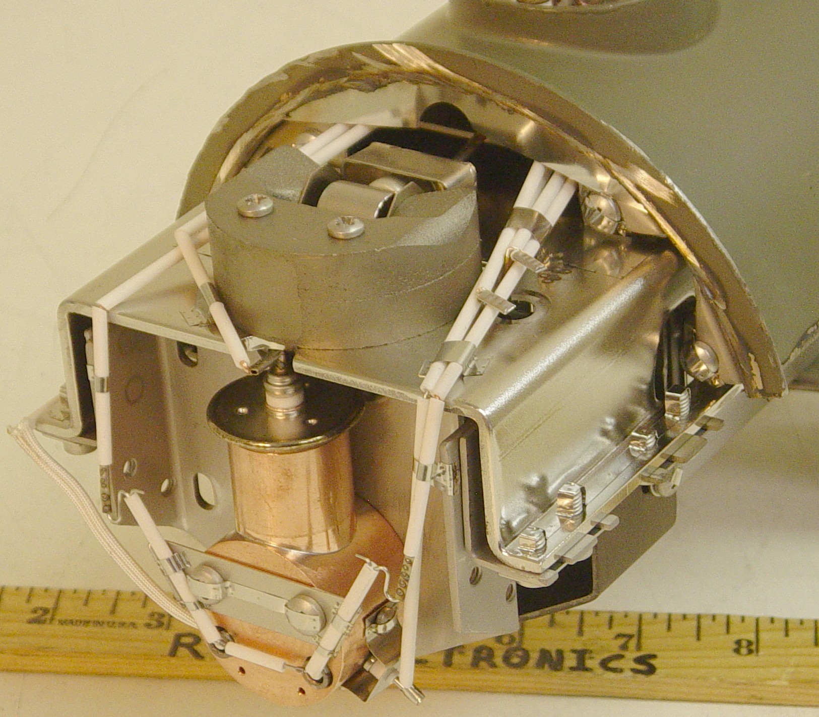
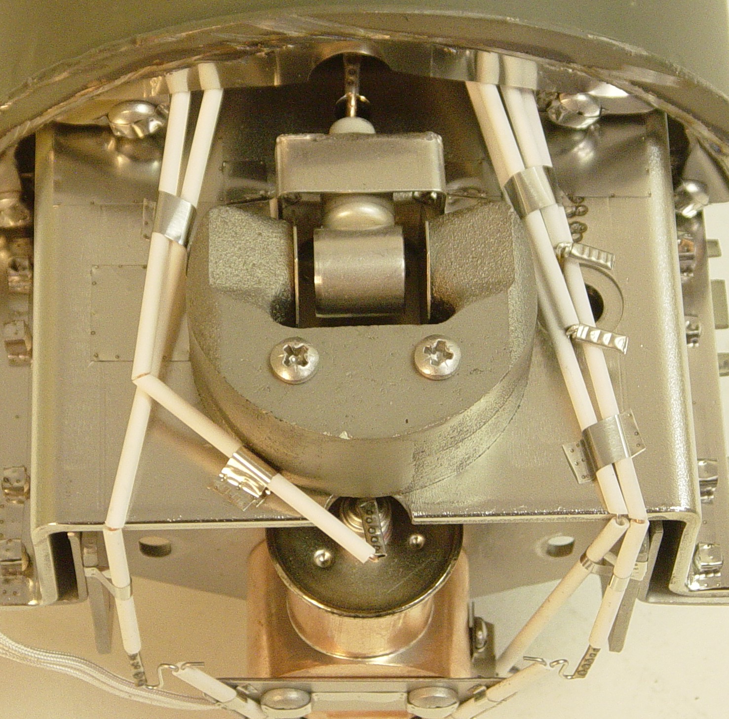
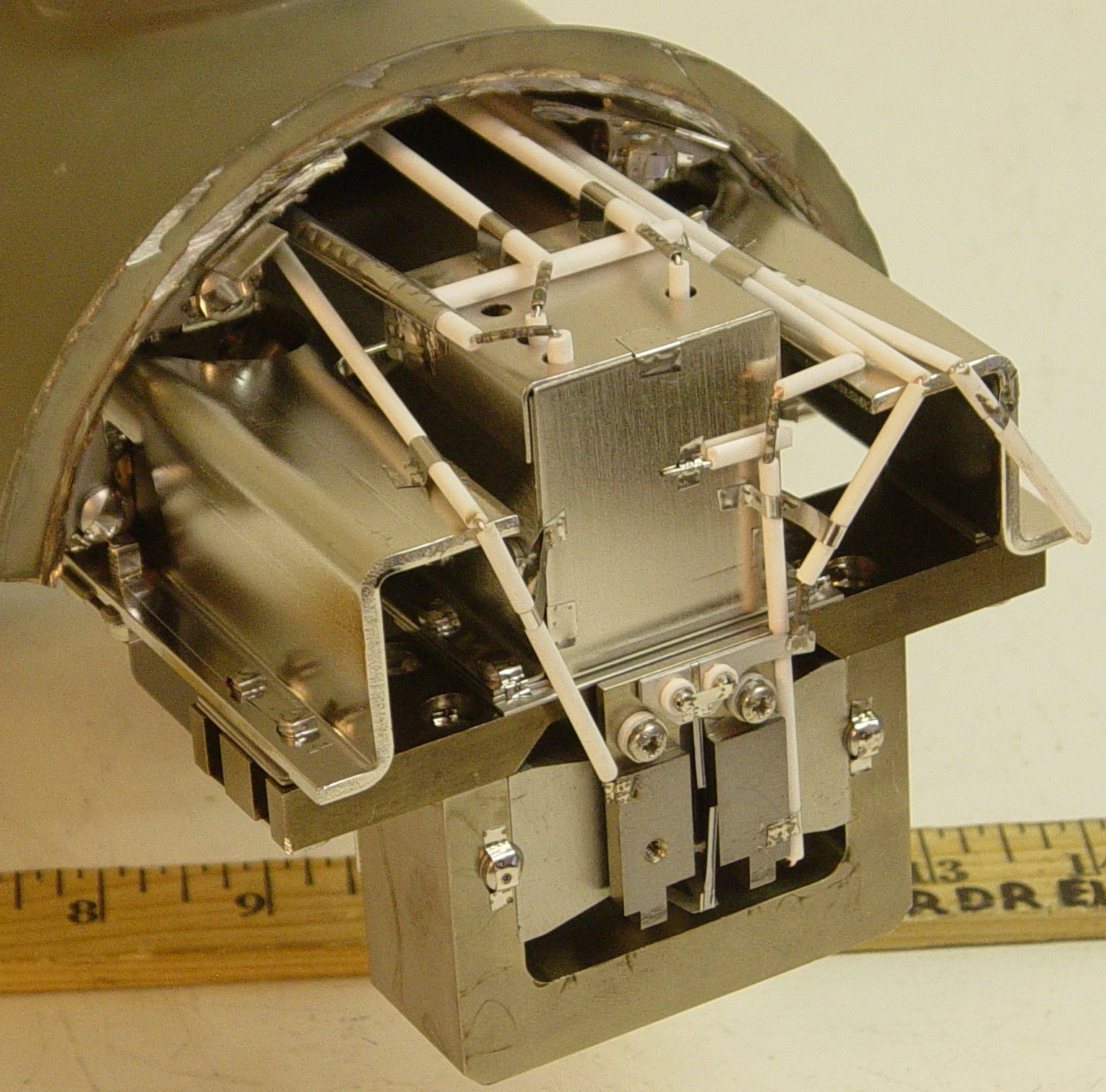
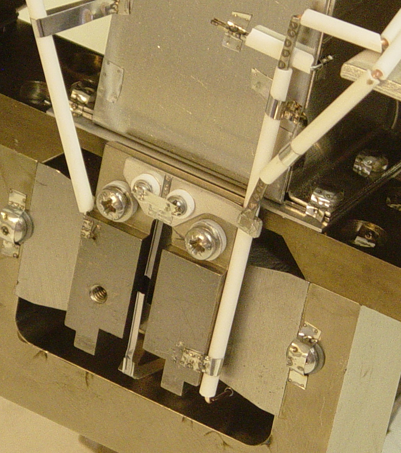
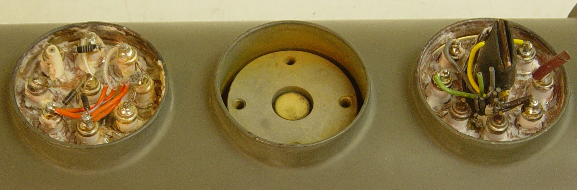
_______________________________________________
time-nuts mailing list -- time-nuts@febo.com
To unsubscribe, go to https://www.febo.com/cgi-bin/mailman/listinfo/time-nuts
and follow the instructions there.