> I've done some Googling and have found any number of designs.

Pat,
1) Safety. I usually use a low voltage step-down transformer. This gives
isolation and safety. Anything from 3 VAC to 24 VAC is fine.
2) Trigger. There are dozens of schematics on the web for capturing the
zero-crossing of a low-voltage sine wave. You can easily go overboard on this.
Or just keep it simple and feed the signal through a resistor directly into a
microprocessor input. The internal clamping diodes do their thing. A Schmitt
trigger input is helpful but not necessary depending on how your software makes
the measurement.
3) Timebase. Given the long-term accuracy of mains (seconds a day, seconds a
year) you don't need an atomic timebase. If you collect data for a couple of
days any old XO will be fine. If you plan to collect data for months you may
want a OCXO. Most of us just use cheap GPS receivers.
4) Measurement. There are many ways to measure the signal. You can measure
frequency directly, as with a frequency counter. You get nice data but it may
not be perfect long-term due to dead time or gating effects in the counter.
So what most of us do is measure phase (time error) instead. One way is to make
time interval measurements from a given mains cycle to a GPS 1PPS tick or vice
versa, from each GPS/1PPS tick to the very next mains cycle. Either way you get
about sample per second. If you're in search of perfection it gets a bit tricky
when the two signals are in a coincidence zone.
The other approach is not to use a frequency or time interval counter at all.
Instead you timestamp each cycle, or every 60th cycle. Unix-like systems have
this capability. See Hal's posting. I use a picPET, a PIC microcontroller that
takes snapshots of a free-running decimal counter driven by a 10 MHz timebase
(OCXO or GPSDO).
The advantage of the timestamp method is that you don't ever miss samples, you
can time every cycle (if you want), or throw away all but one sample per second
or per 10 seconds or per minute, etc. And best of all, timestamping avoids the
hassles of the coincidence zone.
5) CPU. A plain microcontroller, or Arduino, or R-Pi can be used. Or if you're
on Windows and have a native or USB serial port try this simple tool as a demo:
http://leapsecond.com/tools/pctsc.exe
http://leapsecond.com/tools/pctsc.c
6) An assortment of mains links:
http://leapsecond.com/pages/mains/
http://leapsecond.com/pages/mains-cv/
http://wwwhome.cs.utwente.nl/~ptdeboer/misc/mains.html
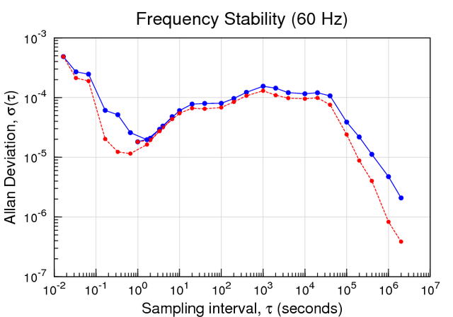
http://leapsecond.com/pages/mains/mains-adev-mdev-gnuplot-g4.png
http://leapsecond.com/pages/tec/mains-clock-ani.gif
http://leapsecond.com/pages/ac-detect/
http://leapsecond.com/pic/picpet.htm
http://leapsecond.com/pic/pp06.htm
7) Final comments.
It is tempting to worry about the design, as they are so many out there on the
web. Which is best? What are the pitfalls? What about noise immunity? What
about precision and accuracy? My recommendation is not to over-think this. Just
throw something together and see what you've got. Most of the work is with
handling the data you get, doing the math, making plots, etc. If after the
first day you see odd-looking 16 ms jumps in your data then you know you need
to pay more attention to trigger level or noise issues.
8) A sound idea.
We need someone to try out the sound card method. Send the isolated low voltage
AC into the L channel and a GPS 1PPS into the R channel. "The rest is just
software." Note that because you have access to the entire sine wave there's a
lot you can do with this method besides making charts of time drift or
frequency deviation from the zero-crossings.
For an even cheaper solution, forget the GPS receiver and the R channel --
since the PC (if running NTP) already knows the correct time. And skip the AC
transformer too -- instead just hang a foot of wire off the L channel input.
There's mains hum everywhere. It would be the one time in your life where the
ever-present audio hum actually has a good use.
/tvb
----- Original Message -----
From: "Patrick Murphy" <[email protected]>
To: <[email protected]>
Sent: Saturday, March 10, 2018 2:53 PM
Subject: [time-nuts] Recommendations for Mains Power Monitor / Logger
All this talk of varying mains power frequency aberrations has me
curious what is happening in my own back yard here in Tulsa in the
USA. Can some recommend a reasonable "introductory level" solution for
this? (As a fledgling Time-Nut, those two words were hard to say.😀)
At the least I would like to watch voltage and frequency, with a
configurable monitoring and logging interval. I can provide precise
timing as needed for synchronization and time-stamping. Expanded
ability to also monitor amperage, various power factors, etc is a plus
but not required at this point.
I've done some Googling and have found any number of designs. What I
can't tell is how well they work. I am pretty handy with my hands and
do not at all mind a DIY solution.
So what do the Oracles say?
Thanks!
-Pat
_______________________________________________
time-nuts mailing list -- [email protected]
To unsubscribe, go to https://www.febo.com/cgi-bin/mailman/listinfo/time-nuts
and follow the instructions there.
_______________________________________________
time-nuts mailing list -- [email protected]
To unsubscribe, go to https://www.febo.com/cgi-bin/mailman/listinfo/time-nuts
and follow the instructions there.