" The radiation toward an elevation angle of 5 degrees shown in the surface
wave plot continues in essentially a straight line, to reach the
ionosphere."
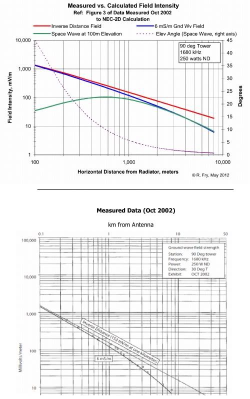
I'm still puzzled by these statements.

What is NEC calculating when one selects the surface field? I am under the
impression that it finds the TOTAL vector field, with no distinction between
parts that are radiated, ground wave, etc. If so, how can you say anything
about radiation continuing in a straight line?

Rather than finding the fields at a single point (x = 100m, z = 9m) for your
5 degree angle, why don't you find them at the series of points
constant*(100, 9)  and plot the radial dependence? Better still, do that for
the Poynting vector.

Jack
WS3N

-----Original Message-----
From: Topband [mailto:[email protected]] On Behalf Of Richard
Fry
Sent: Saturday, September 28, 2013 14:59
To: [email protected]
Subject: Topband: 5/8 wavelength vertical is mo betta than shorter
versions??

Niko Cimbur wrote:
>Sure, over perfect ground the 5/8 wl has 3db more gain at 0 degrees
>elevation. You are talking about theoretical gain.  I am talking about
>real world experience.
___________

Here are a couple of reposts of mine on this subject.

http://s24.postimg.org/6nchfpt1h/NEC_FF_vs_NF_Calcs.jpg

1.  The NEC far-field pattern for 0.1 km linked abovew shows a maximum field
intensity of 590 mV/m at an elevation angle of 23 degrees (the assumed
"takeoff angle").  It  also shows that the field at an elevation angle of 5
degrees is 348 mV/m.

The NEC surface-wave pattern for 0.1 km shows that the maximum field lies in
the horizontal plane rather than at 23 degrees, and is about 890 mV/m rather
than 590 mV/m.

The surface wave analysis also shows that the field radiated toward 5-degree
elevation is about 850 mV/m, rather than the 348 mV/m shown by the far-field
analysis.  Of course, the ratios of these fields are even greater for
elevation angles below 5 degrees, and infinite in the horizontal plane.

It is true that at great distances from a vertical monopole, the radiation
present at low vertical angles is much less than at higher angles.  But that
does not mean that the greater radiation directed at low elevations __as
launched by the monopole__ no longer exists.  The radiation toward an
elevation angle of 5 degrees shown in the surface wave plot continues in
essentially a straight line, to reach the ionosphere.

It is the radiation launched at these low elevation angles that can provide
the greatest single-hop range and fields for skywaves reaching that range,
even though its existence might be unrecognized, or disregarded.


2.  Here is an earlier post of mine on Topband, comparing measured,
real-world fields at the bottom of the page linked below with the fields
calculated by NEC for that same scenario, at the top of the page. The
agreement between the measured groundwave field and the NEC-calculated
groundwave field for this 8 km, 6 mS/m groundwave path is quite good.  It
certainly proves that this monopole is not radiating zero or near zero
fields in/at very low elevation angles, even for earth of rather poor
conductivity.

A common use for correctly defined NEC models shows the electrical
characteristics of the radiator system itself.  But NEC also will show the
field intensities that system will produce at a given distance for a given
applied power, frequency, and earth characteristics -- and do so quite
accurately.

The link below leads to a comparison of the groundwave field measured from a
real-world AM broadcast system by a broadcast consulting engineering firm
vs. the NEC-2D output using those same system parameters.

Included in the NEC analysis is the value of the space wave field at an
elevation of 100 meters above the (level) ground plane, for this
installation -- which should help better understand the points of the
opening post in this thread.

Note that the value of the space wave at 100m elevation and 100m downrange
is lower than the groundwave 100m downrange, and increases as the range
increases.  This is as expected, because the relative field (E/Emax) of the
elevation pattern "launched" by this 1/4-wave monopole reduces as the
elevation angle increases.

Hope this graphic and explanation are useful.

http://i62.photobucket.com/albums/h85/rfry-100/Measured_vs_NEC2D_Fields2.jpg

RF

_________________
Topband Reflector

_________________
Topband Reflector