This discussion on controlling DC motors is like re-inventing the wheel over
and over again.
Let's go back to 2005 when Uli brought out his UHU sevo drive with a small
ATMEL 8 bit micro-controller.
http://uhu-servo.de/servo_en/index.htm
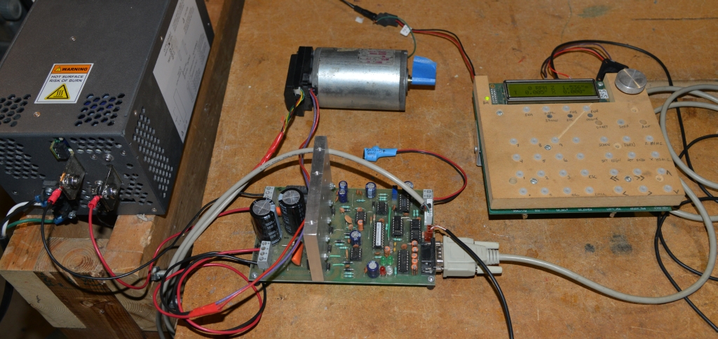
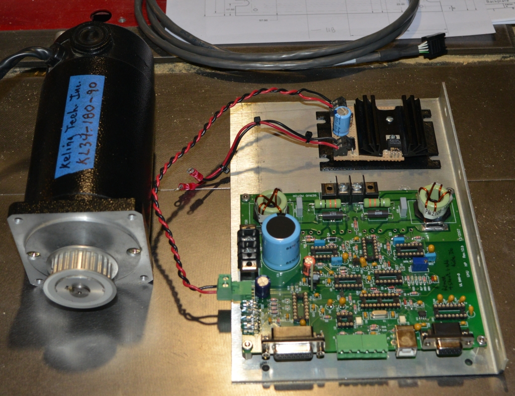
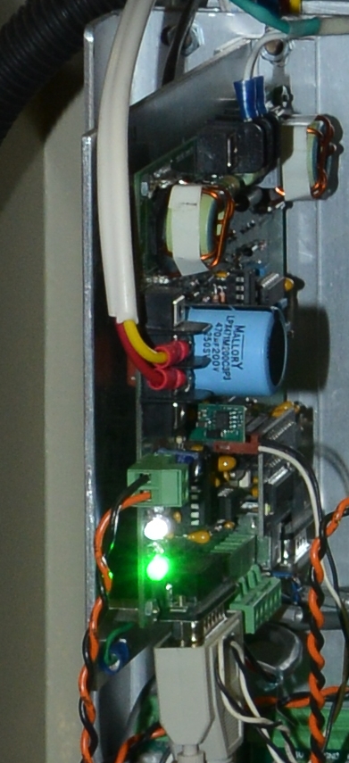
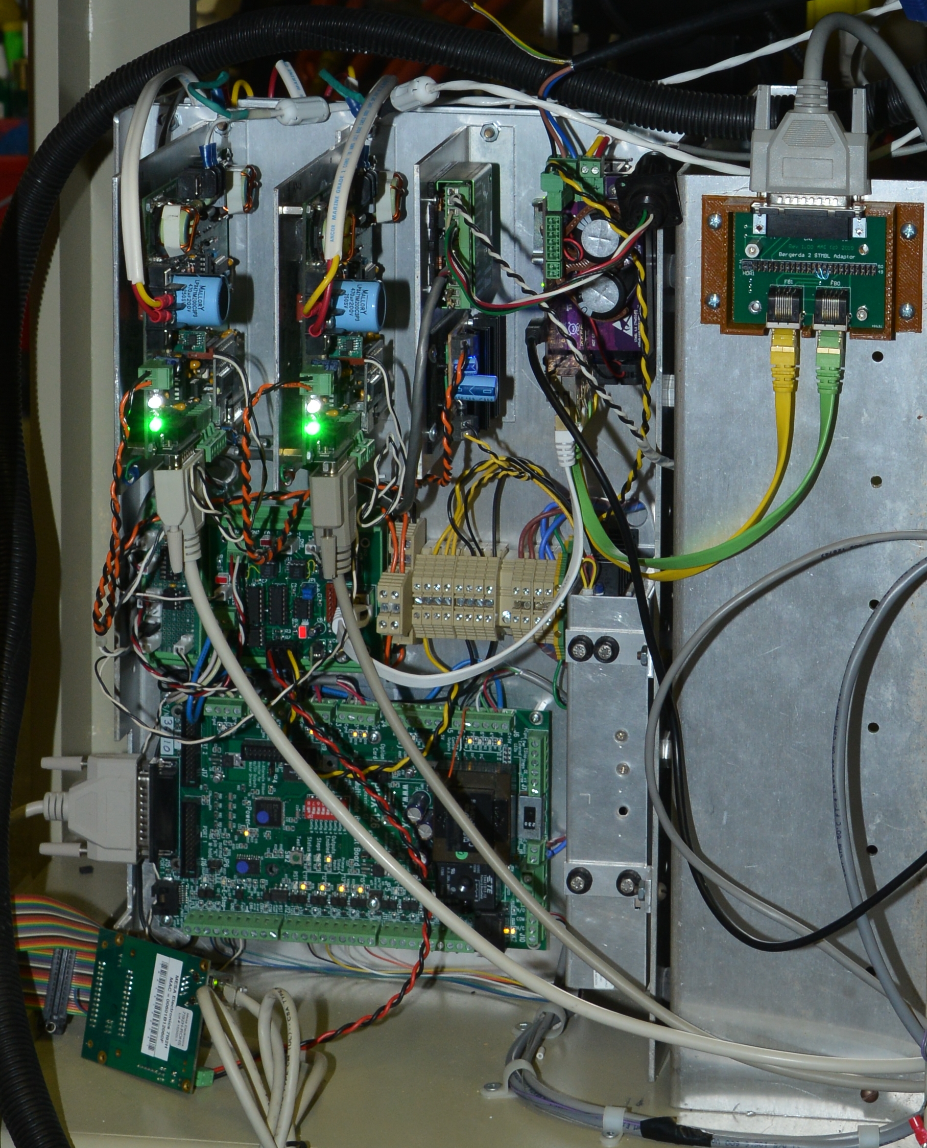
The design was expanded and turned into the more powerful HP_UHU drive.
There's a fair amount of info here:
https://en.industryarena.com/forum/uhu-servo-controllers--411

Take it a step further and Henrik Olsson created the PIC passed replacement for
the ATMEL processor which handled higher line count encoders and is more
resistant to electrical noise.
http://henriksplace.se/servo/

The question was asked about PWM at 50% meaning either 50% of full speed or
motor locked.  The UHU drive concept describing the PWM is not the control
signal from a PC but the drive signal controlling motor speed and direction
using an H-Bridge configuration.

The theory is that if the PWM signal is high the H-Bridge is switched to say
turn the motor clockwise.  If the PWM signal is low the H-Bridge is switch to
turn the motor counter clockwise.  Therefore with 50% the motor is first asked
to turn one way and then the other.  That results in the motor essentially
being locked in place.  Change the PWM on either side of 50% and the turns in
the subsequent direction.

So say the PWM frequency is 100mS for example.  Then for 50mS current is
flowing in one direction and in the other direction for the next 50mS.  In real
life it doesn't happen like that of course.  First the inductance doesn't allow
the motor current to change instantly.  Second, full current as the result of
applied voltage isn't pushed through the windings for the full 50mS.  That
would be like an overheating motor locked condition which is sure to result in
a burned out motor.

So what really happens?  The current through the windings is sensed by the
controller.  If the motor can handle 3 amps continuous then the PWM High/Low
times are modulated by the comparison of sensed motor current against a set
point.   And if the motor is at the commanded position as determined by the
encoder that current may be set back to reduce heating.

But move the motor off position as sensed by the encoder and the PWM on the
side opposite to rotation is increased as well as perhaps the setback current.

Here's a photo of my original UHU drive on a PC board made by Manjeet in India.
  The motor is a 24V DC Servo with encoder.
http://www.autoartisans.com/ELS/doc/Test_UHU.jpg

I then ordered 4 and assembled 2 of the HP_UHU kits.
http://www.autoartisans.com/ELS/doc/HP_UHU.jpg

Ultimately I did have noise issues with the brushed servos and bought two of
the modules from Henrik.  You can just see the small piggy back board in this
photo.
http://www.autoartisans.com/ELS/doc/Henrik_HP_UHU_Module.jpg

The zoomed in photo is of the Mill Control Cabinet.
http://www.autoartisans.com/ELS/doc/ControlCabinet.jpg
Two HP_UHU DC Servo drives with Henrik's processor module.  To the right of
that a 15V small power supply for the UHU Logic section and behind that a GECKO
Stepper Driver for the knee.  And beside that the STMBL AC Servo drive.

Another option for a complete closed loop step/dir DC servo driver is the GECKO
320 I think.  I have two but have never actually tried them.  The DC motors I
have are 90VDC and I run them with a 105VDC power supply.  The GECKO's were
limited to 70 or 80V.

I'm sure there are some other DC Motor Driver with encoder feedback out there.

John Dammeyer


> -----Original Message-----
> From: Thaddeus Waldner [mailto:thadw...@gmail.com]
> Sent: October-15-20 2:18 PM
> To: Enhanced Machine Controller (EMC)
> Subject: Re: [Emc-users] question for Chris and Thaddeus
>
> The reactance and inductance questions are above my pay grade and I�d be
> happy to hear someone explain it. :) I use these for
> robotics class in place of the old BJT L298, which are optimistically rated
> for 2 amps but have more than 2v drop at much less than
> that current.
>
> Maybe I don�t understand your comment but I�m pretty sure that a 50% duty
> cycle PWM waveform will run the motor at half-
> voltage.
>
> You command the direction with INa and INb according to the Truth Table. The
> PWM signal will then switch either the A or B low-
> side FETs, depending on the INa/INb configuration.
>
>
> > It would appear that when enabled, and lets say with a pwm frequency near
> > the top of the 10khz range, that a 50% duty cycle pwm waveform would be
> > the equ of a balanced, at rest servo, so my first question is how much
> > additional inductance in series with the motors leakage reactance will
> > be needed to protect the chip from the current surges at the pwm
> > waveforms transition points?
> >
> > My hal file will obviously need to stage an initial enable at the 50%
> > duty points, then let the pid output thru.
>
>
>
>
> _______________________________________________
> Emc-users mailing list
> Emc-users@lists.sourceforge.net
> https://lists.sourceforge.net/lists/listinfo/emc-users


_______________________________________________
Emc-users mailing list
Emc-users@lists.sourceforge.net
https://lists.sourceforge.net/lists/listinfo/emc-users