You just embed a SubScene within a 3D scene, or a SubScene3D within a 2D scene,
etc. So you can easily nest one rendering mode within the other -- where
"easily" means, that each SubScene / SubScene3D has the semantics of "draw into
a texture and composite into the parent scene".
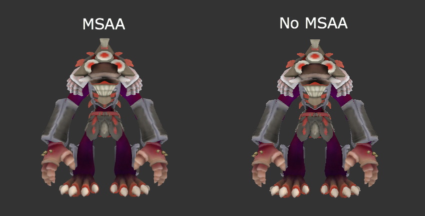
Richard

On Jul 18, 2013, at 2:20 PM, Daniel Zwolenski <[email protected]> wrote:

> Does it need to be a separate class, can it not just be a setting on scene
> like setRenderMode(3d)? Just thinking you may want a base 3d view for example
> but then show 2d screens at times for settings, etc, so you could switch it
> on and off.
>
> I assume there's no way to do it pane by pane, so the docked components of a
> BorderPane are 2d optimized but the center is 3d? Or is that what SubScene3d
> is for (not real clear how this would be used)?
>
>
>
> On 19/07/2013, at 6:58 AM, Richard Bair <[email protected]> wrote:
>
>> While working on RT-5534, we found a large number of odd cases when mixing
>> 2D and 3D. Some of these we talked about previously, some either we hadn't
>> or, at least, they hadn't occurred to me. With 8 we are defining a lot of
>> new API for 3D, and we need to make sure that we've very clearly defined how
>> 2D and 3D nodes interact with each other, or developers will run into
>> problems frequently and fire off angry emails about it :-)
>>
>> Fundamentally, 2D and 3D rendering are completely different. There are
>> differences in how opacity is understood and applied. 2D graphics frequently
>> use clips, whereas 3D does not (other than clipping the view frustum or
>> other such environmental clipping). 2D uses things like filter effects (drop
>> shadow, etc) that is based on pixel bashing, whereas 3D uses light sources,
>> shaders, or other such techniques to cast shadows, implement fog, dynamic
>> lighting, etc. In short, 2D is fundamentally about drawing pixels and
>> blending using the Painters Algorithm, whereas 3D is about geometry and
>> shaders and (usually) a depth buffer. Of course 2D is almost always defined
>> as 0,0 in the top left, positive x to the right and positive y down, whereas
>> 3D is almost always 0,0 in the center, positive x to the right and positive
>> y up. But that's just a transform away, so I don't consider that a
>> *fundamental* difference.
>>
>> There are many ways in which these differences manifest themselves when
>> mixing content between the two graphics.
>>
>> http://fxexperience.com/?attachment_id=2853
>>
>> This picture shows 4 circles and a rectangle. They are setup such that all 5
>> shapes are in the same group [c1, c2, r, c3, c4]. However depthBuffer is
>> turned on (as well as perspective camera) so that I can use Z to position
>> the shapes instead of using the painter's algorithm. You will notice that
>> the first two circles (green and magenta) have a "dirty edge", whereas the
>> last two circles (blue and orange) look beautiful. Note that even though
>> there is a depth buffer involved, we're still issuing these shapes to the
>> card in a specific order.
>>
>> For those not familiar with the depth buffer, the way it works is very
>> simple. When you draw something, in addition to recording the RGBA values
>> for each pixel, you also write to an array (one element per pixel) with a
>> value for every non-transparent pixel that was touched. In this way, if you
>> draw something on top, and then draw something beneath it, the graphics card
>> can check the depth buffer to determine whether it should skip a pixel. So
>> in the image, we draw green for the green circle, and then later draw the
>> black for the rectangle, and because some pixels were already drawn to by
>> the green circle, the card knows not to overwrite those with the black pixel
>> in the background rectangle.
>>
>> The depth buffer is just a technique used to ensure that content rendered
>> respects Z for the order in which things appear composited in the final
>> frame. (You can individually cause nodes to ignore this requirement by
>> setting depthTest to false for a specific node or branch of the scene graph,
>> in which case they won't check with the depth buffer prior to drawing their
>> pixels, they'll just overwrite anything that was drawn previously, even if
>> it has a Z value that would put it behind the thing it is drawing over!).
>>
>> For the sake of this discussion "3D World" means "depth buffer enabled" and
>> assumes perspective camera is enabled, and 2D means "2.5D capable" by which
>> I mean perspective camera but no depth buffer.
>>
>> So:
>>
>>   1) Draw the first green circle. This is done by rendering the circle into
>> an image with nice anti-aliasing, and then rotating that image
>>            and blend with anything already in the frame buffer
>>   2) Draw the magenta circle. Same as with green -- draw into an image with
>> nice AA and rotate and blend
>>   3) Draw the rectangle. Because the depth buffer is turned on, for each
>> pixel of the green & magenta circles, we *don't* render
>>        any black. Because the AA edge has been touched with some
>> transparency, it was written to the depth buffer, and we will not
>>        draw any black there. Hence the dirty fringe! No blending!
>>   4) Draw the blue circle into an image with nice AA, rotate, and blend. AA
>> edges are blended nicely with black background!
>>   5) Draw the orange circle into an image with nice AA, rotate, and blend.
>> AA edges are blended nicely with black background!
>>
>> Transparency in 3D is a problem, and on ES2 it is particularly difficult to
>> solve. As such, it is usually up to the application to sort their scene
>> graph nodes in such a way as to end up with something sensible. The
>> difficulty in this case is that when you use any 2D node and mix it in with
>> 3D nodes (or even other 2D nodes but with the depth buffer turned on) then
>> you end up in a situation where the nice AA ends up being a liability rather
>> than an asset -- unless you have manually sorted all your nodes in such a
>> way as to avoid the transparency problems.
>>
>> There are other problems. Suppose you create a scene where you have 3
>> Rectangles, with Z values:
>>
>> r1.setTranslateZ(10);
>> r2.setTranslateZ(20);
>> r3.setTranslateZ(30);
>>
>> g1 = [r2, r3]
>> g2 = [g1, r1]
>>
>> If you have the depth buffer turned on, then you would expect that r1 is
>> drawn on top of r2, which is drawn on top of r3, regardless of the presence
>> of groups, because the order in which things are rendered is independent of
>> the order in which they appear, since we're using a depth buffer, so the Z
>> values are the only thing that really dictates the order in which things
>> appear.
>>
>> Now, something weird is going to happen if I either apply an effect, clip,
>> blendMode, or turn node caching on to g1. Because all 4 of these properties
>> are 2D properties that by their nature result in "flattening". That is, they
>> take the scene graph they've been given and render to an intermediate image,
>> and are then composited into the rest of the scene. In this case, since g1
>> has no Z translation, what you would get is the combination of r2 and r3
>> drawn on top of r1! We've flattened r2 and r3 into an image which is then
>> rendered at Z=0, which is above r1 with z=10.
>>
>> This behavior, although surprising, is consistent and correct. But it sure
>> is surprising for those, who like me, are traditional 2D developers coming
>> to the 3D world!
>>
>> Then there is the new support for scene anti-aliasing (presently using
>> multi-sampling, referred to as MSAA . In our 2D rendering, we always
>> anti-alias all shapes using a special set of shaders and grayscale masks
>> generated in software. This is a common technique and produces objectively
>> the best AA money can buy, often with the least overhead (the cost is in
>> generating and uploading the masks, which for most things we've optimized
>> the heck out of, though for paths you still will run into the worst case
>> scenarios). MSAA on the other hand, applies an algorithm against the entire
>> scene in order to produce "automatic" AA on everything (there are many ways
>> to do scene anti-aliasing. One way you can think of would be to draw to a
>> buffer 4x or 8x as large as necessary, and then scale it down using bilinear
>> scaling to 1x and put that on the screen, letting the image scaling
>> algorithm do the work).
>>
>> https://wiki.mozilla.org/images/4/48/Msaa_comparison.png
>>
>> Here you can see the smoothed edges of the monster. However MSAA does take
>> extra cycles and on resource constrained devices you may not want to do this
>> at all. In addition, it gives you worse AA than you would get with our mask
>> / shader approach for 2D shapes.
>>
>> Also, opacity. In 2D rendering contexts, using opacity means "render to an
>> image and apply the alpha blend to the entire image". This also inherently
>> means flattening. In 3D contexts, if you put an alpha on a Group, it should
>> mean "multiply this alpha with the alpha of each of my children
>> individually". This would always give the wrong result in 2D, but generally
>> the right one in 3D. And certainly better than flattening a group, which is
>> pretty much always a problem.
>>
>> So in summary, if you use 2D APIs in a 3D world (effect, clip, blendMode,
>> node caching) then you get surprising results. If you use a 2D shape in a 3D
>> world then the nice AA of 2D shapes may end up good or bad depending on the
>> render order relative to depth. And depending on whether you use a parallel
>> or perspective camera, using 3D shapes in a 2D world may end up quite
>> surprising as well.
>>
>> So what do I propose to do about this? Well, we can leave it be and just
>> document the heck out of it. Or we can try to tease apart the scene graph
>> into Node, Node3D, and NodeBase. Right now we're doing the former, and I've
>> tried the latter and it makes a mess in many places. We can talk about those
>> alternatives if you like, but to shorten (ahem) this message, I'm going to
>> just say it doesn't work (at least, it doesn't work well and may not work at
>> all) and leave it at that.
>>
>> Instead I propose that we keep the integrated scene graph as we have it, but
>> that we introduce two new classes, Scene3D and SubScene3D. These would be
>> configured specially in two ways. First, they would default to depthTest
>> enabled, scene antialiasing enabled, and perspective camera. Meanwhile,
>> Scene and SubScene would be configured for 2.5D by default, such that
>> depthTest is disabled, scene AA is disabled, and perspective camera is set.
>> In this way, if you rotate a 2.5D shape, you get perspective as you would
>> expect, but none of the other 3D behaviors. Scene3D and SubScene3D could
>> also have y-up and 0,0 in the center.
>>
>> Second, we will interpret the meaning of opacity differently depending on
>> whether you are in a Scene / SubScene, or a Scene3D / SubScene3D. Over time
>> we will also implement different semantics for rendering in both worlds. For
>> example, if you put a 2D rectangle in a Scene3D / SubScene3D, we would use a
>> quad to represent the rectangle and would not AA it at all, allowing the
>> scene3D's anti-aliasing property to define how to handle this. Likewise, a
>> complex path could either be tessellated or we could still use the mask +
>> shader approach to filling it, but that we would do so with no AA (so the
>> mask is black or white, not grayscale).
>>
>> If you use effects, clips, or blendModes we're going to flatten in the 3D
>> world as well. But since these are not common things to do in 3D, I find
>> that quite acceptable. Meanwhile in 3D we'll simply ignore the cache
>> property (since it is just a hint).
>>
>> So the idea is that we can have different pipelines optimized for 2D or 3D
>> rendering, and we will key-off which kind to use based on Scene / Scene3D,
>> or SubScene / SubScene3D. Shapes will look different depending on which
>> world they're rendered in, but that follows. All shapes (2D and 3D) will
>> render by the same rules in the 3D realm.
>>
>> Thoughts?
>>
>> Richard
>>
>>