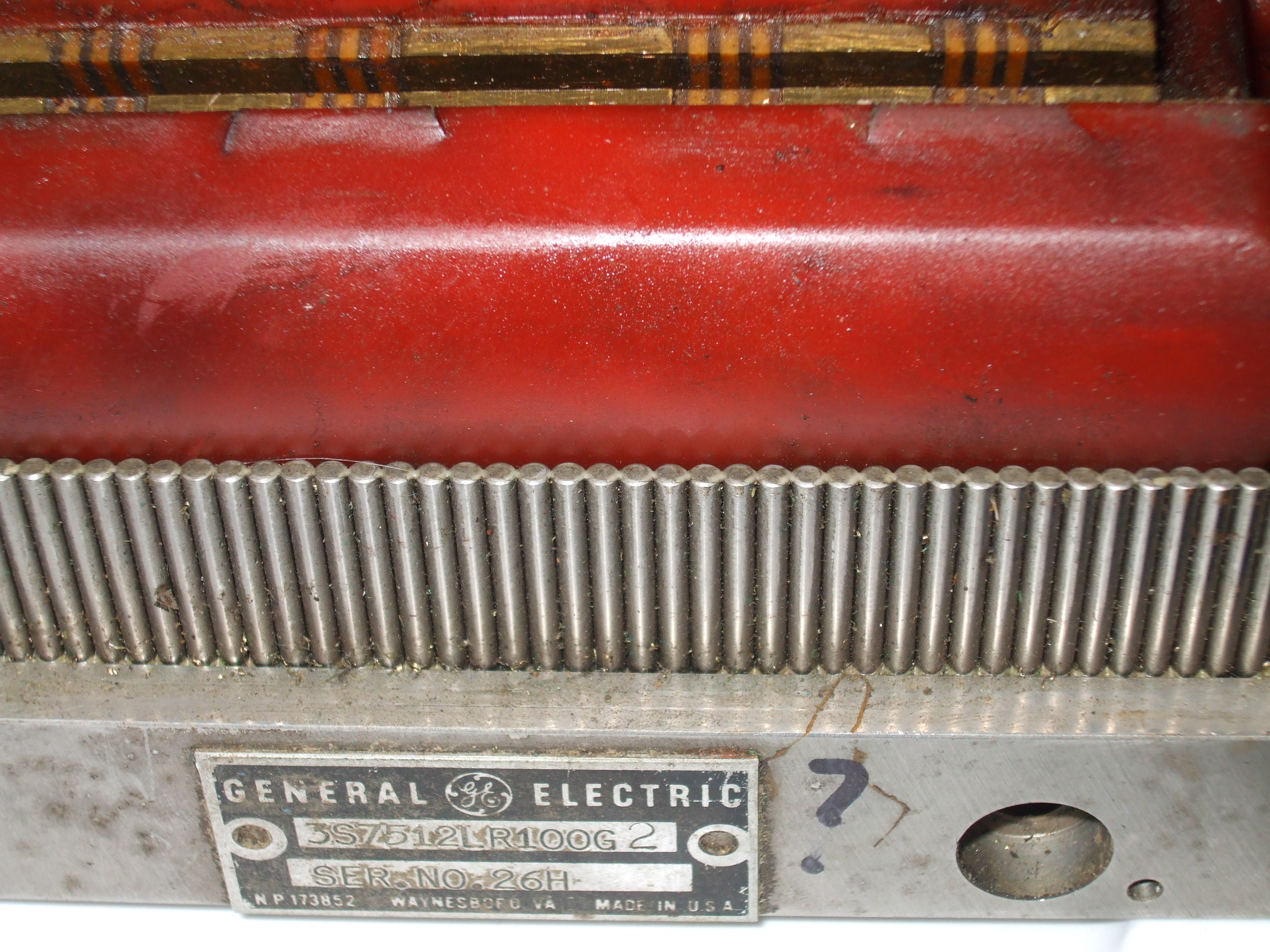
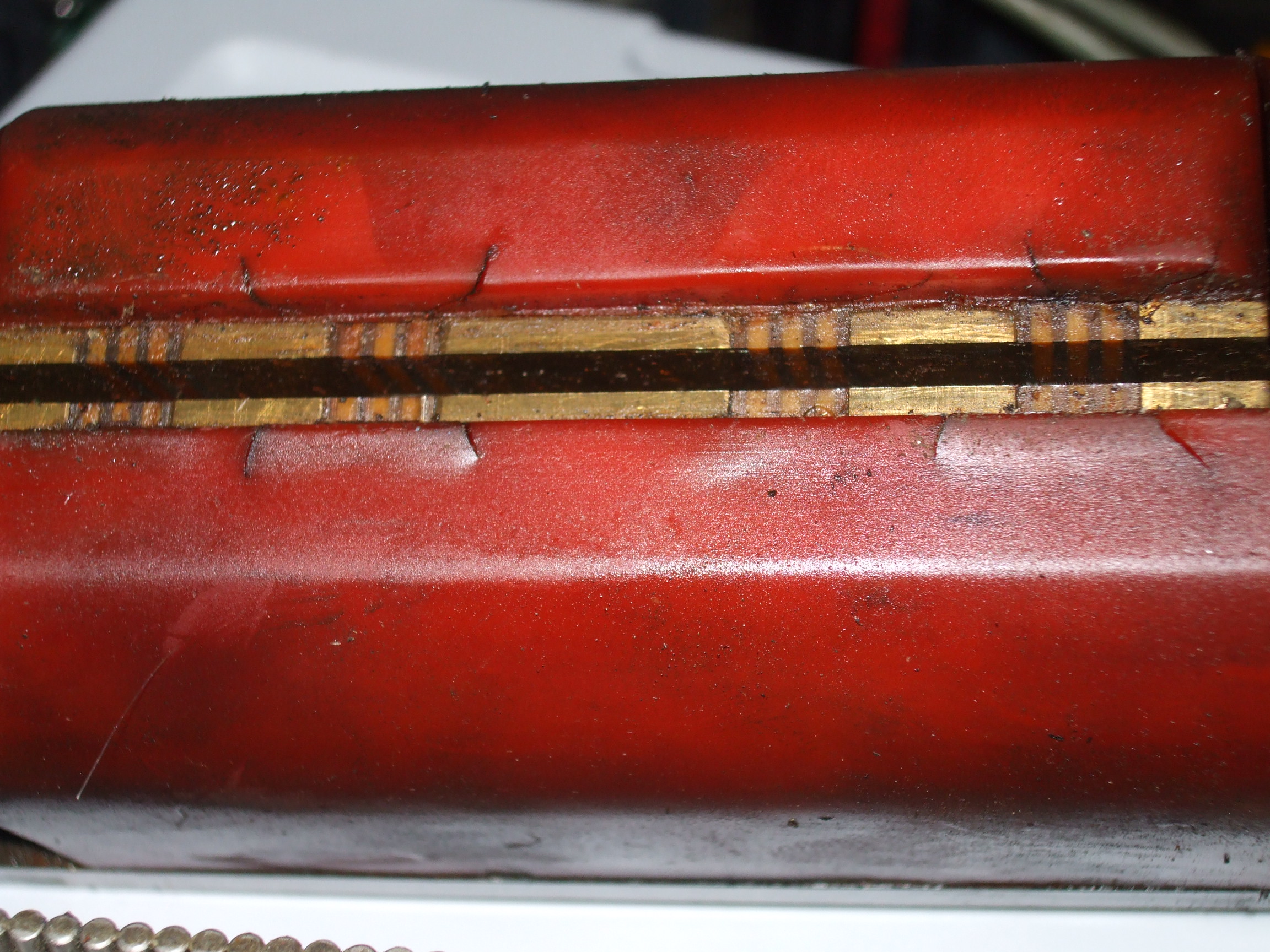
Here are some more pictures...  (top red thing is the read head)
http://electronicsam.com/images/KandT/conversion/accpinset1.jpg
http://electronicsam.com/images/KandT/conversion/accpinset.jpg
This is how I understand it as of today.... ;)

There are 4 coils - they are hooked up in a center tap config (see
schem) - 2 sets of 2 coils. An excitation signal (250khz square wave) is
sent to the outside connections of the 2 center tapped coils. The center
taps are summed together and turned into a square wave. That square wave
is shifted compared to the exciter signal depending on the position
relative to the .1 pin.

Now the way I think the controller did it was this - it had a 250khz
clock - they used this to count the shift between the exciter signal and
the summed square wave back from the center taps. this would give you
250khz/250hz - 1000 divisions within each pin.

thanks
sam


On 4/11/2010 08:03 PM, Jon Elson wrote:
> sam sokolik wrote:
>
>> there are actually 4 coils.  Each head has 2 shielded cables coming from
>> the head - each cable has 4 conductors + shield.  At the controller  -
>> the 2 coils on each cable are hooked together to form a center tapped
>> setup.   (agian - if I have it right - they excite the 2 outside
>> connections of the 2 center tapped hookups - then the center taps get
>> summed together and shaped. this from trying to read the desciption on
>> the schematic I scanned - plus you can see the coil hookups) :)
>>
>>
> I don't know, looking at the jpg of the schematic, it doesn't really
> look like the windings will work the way you want for the AD chip.  It
> really doesn't look like there is an excitation winding and a pair of
> sense windings.  With 114 Ohms per coil, the drive requirement can't be
> terribly high, so that may not be a problem.  If the AD chip can be made
> to work, the resolution will be 4096 counts per period of the teeth on
> the long scale.  That probably is OK, as I think these teeth are about
> 10 per inch.  Ah, yes, I see it IS a GE Accupin scale, I had already
> guessed it might be from your description.  The way one of these schemes
> worked is they drove sine-wave signals in quadrature to the two sin/cos
> windings, and then looked at the time of the zero crossing on the other
> winding.  That told the position of the windings relative to each
> other.  This one almost sounds like it works the same way, but the
> description says square wave.  So, maybe they are using some analog
> scheme to also sense the voltage of the output as well as the phase.
>
> Anyway, it looks like this may be fairly hard to make work.
>
> Jon
>
> ------------------------------------------------------------------------------
> Download Intel® Parallel Studio Eval
> Try the new software tools for yourself. Speed compiling, find bugs
> proactively, and fine-tune applications for parallel performance.
> See why Intel Parallel Studio got high marks during beta.
> http://p.sf.net/sfu/intel-sw-dev
> _______________________________________________
> Emc-users mailing list
> [email protected]
> https://lists.sourceforge.net/lists/listinfo/emc-users
>
>

------------------------------------------------------------------------------
Download Intel® Parallel Studio Eval
Try the new software tools for yourself. Speed compiling, find bugs
proactively, and fine-tune applications for parallel performance.
See why Intel Parallel Studio got high marks during beta.
http://p.sf.net/sfu/intel-sw-dev
_______________________________________________
Emc-users mailing list
[email protected]
https://lists.sourceforge.net/lists/listinfo/emc-users