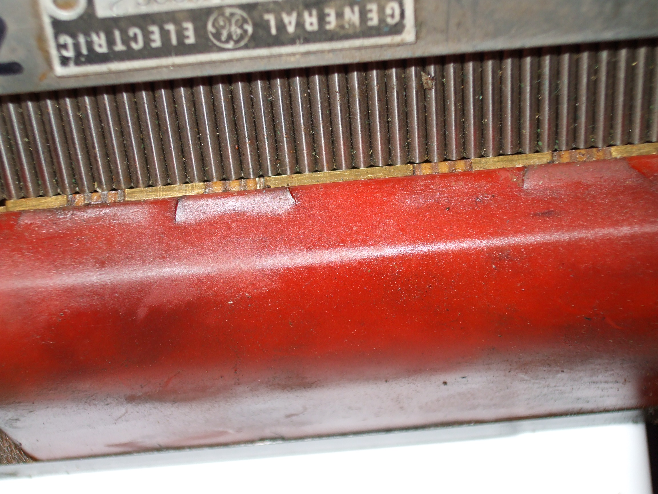
On 16 April 2010 15:19, sam sokolik <[email protected]> wrote:
>
> Here is how the head lines up with the pins (showing that 2 heads line
> up and 2 are .05 off.)
> http://electronicsam.com/images/KandT/conversion/accupinlineup.jpg
I was just about to ask that question...

The inductance of each coil depends on how its laminations are aligned
with the pins, and the schematic text mentions that they are in a
bridge relationship.

So, this looks like a Wheatstone Bridge, as used for strain gauges,
but an inductive rather than resistive one.

Not so odd, I made a successful non-contacting displacement transducer
once which used two co-axial tubes as one arm of an LC bridge, this is
pretty much the same I think, but using only inductors and possibly
resistors.

http://www.allaboutcircuits.com/vol_2/chpt_12/5.html

Might contain some clues.

However, I think just applying a 250Hz square wave and an oscilloscope
should at least tell you what comes out of the terminals and then you
can figure it out from there. A $15 Arduino with a power OP amp can
produce the excitation, sample the output, time it to 62nS resolution
and convert it to encoder-style pulses.

I suspect that Audacity and your PC sound card would work as an
excitation source for initial experimentation.

--
atp

------------------------------------------------------------------------------
Download Intel® Parallel Studio Eval
Try the new software tools for yourself. Speed compiling, find bugs
proactively, and fine-tune applications for parallel performance.
See why Intel Parallel Studio got high marks during beta.
http://p.sf.net/sfu/intel-sw-dev
_______________________________________________
Emc-users mailing list
[email protected]
https://lists.sourceforge.net/lists/listinfo/emc-users