Kirk Wallace wrote:
> I would like to make gears, but I need to know the tooth shape in order
> to make a form tool or cut an outline. This is what I came up with, if
> there are any mistakes or bad assumptions, please let me know.
>
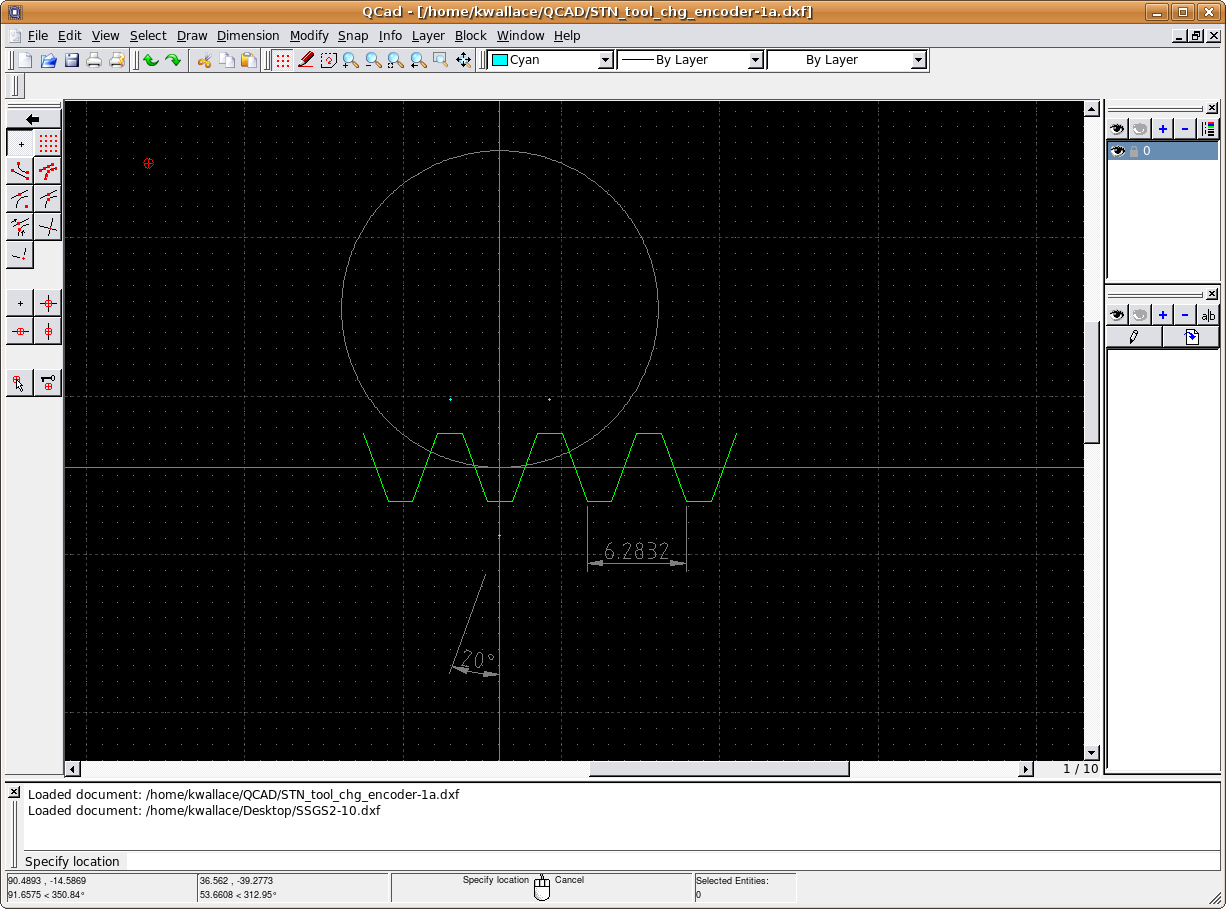
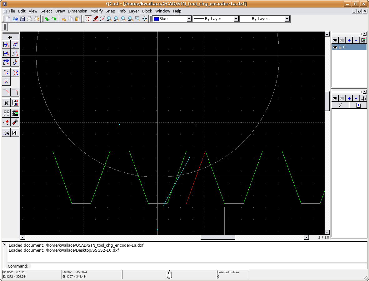
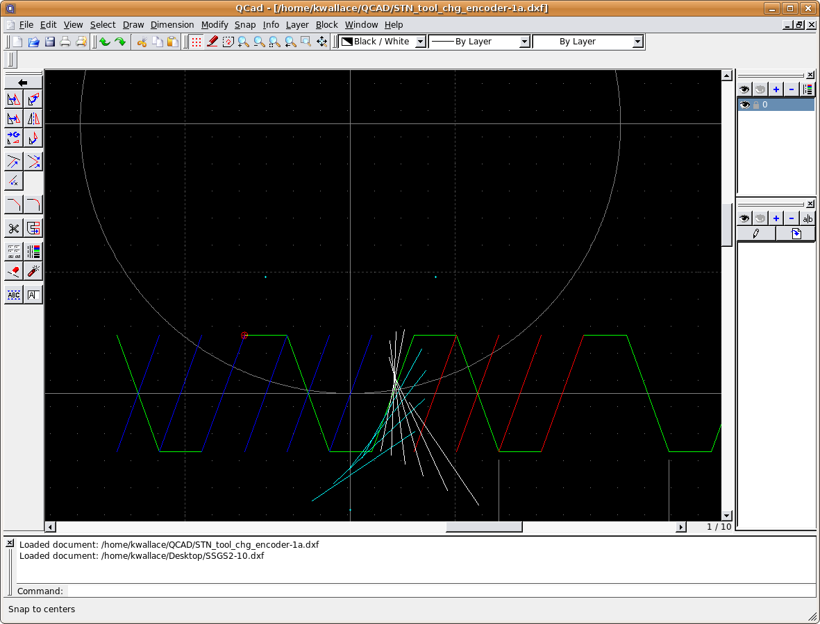
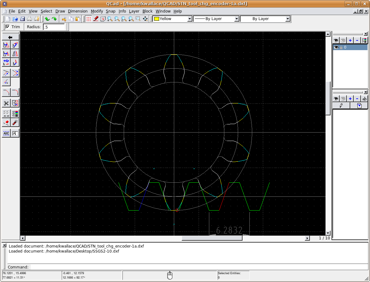
I'm no gear expert, but I have a few comments.  The only gears I've made
are worm gears, and I hobbed them so the tooth shape was generated
automatically.

> I referenced:
> http://en.wikipedia.org/wiki/Gear
> http://en.wikipedia.org/wiki/Involute_gear
> http://en.wikipedia.org/wiki/Involute
> http://en.wikipedia.org/wiki/Rack_and_pinion
>
> My example gear is a 2m(module) pitch - 20mm.
>
> A sample is on this page:
> http://www.qtcgears.com/RFQ/default.asp?Page=../KHK/newgears/KHK044.html
> (Short URL) http://alturl.com/whp2
>
> Pitch is the tooth length, but expressed in pitch circle diameter, so a
> 10 tooth gear with a 20mm pitch circle = 20mm/10t = 2, but this is not
> the linear tooth length. I believe the basis for involute gears is the
> trapezoidal rack, so I need the linear tooth length, which should be 2
> module x pi. A common pressure angle is 20 degrees. I assumed the rack
> base and top are horizontally midway between the rack center line and
> the 20 degree peaks, such that the X length of the rise, flats and falls
> are equal. Here is my rack and pitch circle:

I think that assumption might not be valid.  I believe the height above
the pitch line, and the depth below the pitch line have names - addendum
and dedendum IIRC, and they are not necessarily equal to each other.  In
particular, for a pinion with a small tooth count like yours, the
dedendum is made less to avoid undercutting the teeth - the undercut
shows up in your last image.  That would result in weak teeth if the
gear was heavily stressed.

> http://www.wallacecompany.com/machine_shop/gears/rack_and_pitch_circle.png
> (Short URL) http://alturl.com/7t8a
>
> The first pinion tooth form guess is the complementary shape of the rack
> tooth, but as the rack moves the pinion rotates and lifts, so the pinion
> tooth shape needs to change to take the trapezoidal shape that matches
> the rotation and lift. If I move the rack one quarter of a tooth the
> pinion will rotate a proportionate angle.
> 1/4t = 1.5708mm
> C = pi x D = pi x 20mm = 62.832mm = 360 degrees
> 360deg x 1.5708mm/62.832mm = 9 degrees per 1/4t
>
> If I move the rack shape 1/4t to the right, then rotate it 9 deg
> clockwise back to the home position, the mesh point will be somewhere on
> the new shape.
>
> http://www.wallacecompany.com/machine_shop/gears/rack_and_quarter_tooth.png
> (Short URL) http://alturl.com/gd75
>
> If I continue the process, I'll have more mesh points.
>
> http://www.wallacecompany.com/machine_shop/gears/rack_and_pinion_shape.png
> (Short URL) http://alturl.com/54oj
>
> I can then trim the lines, mirror the shape on the tooth center line,
> guess at a tip and base clearance shape.
>
> http://www.wallacecompany.com/machine_shop/gears/gear.png
> (Short URL) http://alturl.com/cqcw
>
> The problem is, have I made any mistakes? Is there a better, easier way?

I think your derivation of the shape is correct.  There is probably a
mathematically purer way (one that doesn't involve small increments of
motion that you then blend into the form).  But I like your way better.

Note that what you did on paper is what happens in metal when you hob a
gear.  Imagine that your rack is actually one side of an acme threaded
rod.  Since the screw threads are helical, not just rings around the
rod, the "rack" teeth are inclined where they meet the gear.  So you
have to lift one end of the rod out of the paper, until the helix angle
is canceled out.

Then you cut flutes on the rod, and spin both rod and gear blank, so you
get the effect of the gear rolling along the "rack".  Finally, you
slowly feed the rod across the face of the gear.

The other approach is to buy a gear cutter with the proper form.  Note
that unlike a hob (which can be used to cut gears with any number of
teeth), a gear cutter is designed for a specific range of teeth.  I
think there is usually a set of 8 to cut everything from 12 tooth
pinions thru many tooth gears up to a rack (basically a gear with an
infinite number of teeth).

Regards,

John Kasunich


------------------------------------------------------------------------------
The NEW KODAK i700 Series Scanners deliver under ANY circumstances! Your
production scanning environment may not be a perfect world - but thanks to
Kodak, there's a perfect scanner to get the job done! With the NEW KODAK i700
Series Scanner you'll get full speed at 300 dpi even with all image
processing features enabled. http://p.sf.net/sfu/kodak-com
_______________________________________________
Emc-users mailing list
[email protected]
https://lists.sourceforge.net/lists/listinfo/emc-users