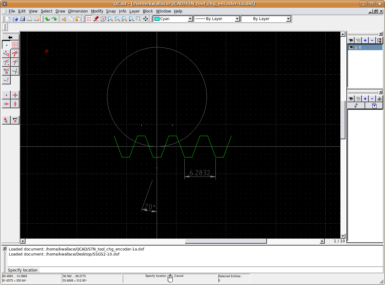
Kirk Wallace wrote:
> On Sat, 2009-05-09 at 15:07 -0400, John Kasunich wrote:
>
>> Kirk Wallace wrote:
>>
> ... snip
>
>> I assumed the rack
>>
>>> base and top are horizontally midway between the rack center line and
>>> the 20 degree peaks, such that the X length of the rise, flats and falls
>>> are equal. Here is my rack and pitch circle:
>>>
>> I think that assumption might not be valid.  I believe the height above
>> the pitch line, and the depth below the pitch line have names - addendum
>> and dedendum IIRC, and they are not necessarily equal to each other.  In
>> particular, for a pinion with a small tooth count like yours, the
>> dedendum is made less to avoid undercutting the teeth - the undercut
>> shows up in your last image.  That would result in weak teeth if the
>> gear was heavily stressed.
>>
>
> A thought I had on this, is that for different gears of the same pitch
> to work together they need to have the same base rack form. Since a gear
> and it's mate can be derived from the top or bottom of the base rack
> form, the base form should be symmetrical. A non-symmetrical base form
> could be used, but I think the gear pair will only work with its
> original mate. Actually, the more I think, the rack base and top lines
> don't even count, because the mesh zone is well within these limits. I
> could do the derivation again with a sawtooth instead of a trapezoidal
> form. I suspect the way to adjust the addendum/dedendum is with pressure
> angle, but this is just a hunch at this point. I think I have enough to
> make what I need, so I'm not sure how far I'll get on this issue. Some
> engineers have made a life on these matters, I've only got spare time.
>
>
>>> http://www.wallacecompany.com/machine_shop/gears/rack_and_pitch_circle.png
>>> (Short URL) http://alturl.com/7t8a
>>>
>>> The first pinion tooth form guess is the complementary shape of the rack
>>>
> ... snip
>
>>> The problem is, have I made any mistakes? Is there a better, easier way?
>>>
>> I think your derivation of the shape is correct.  There is probably a
>> mathematically purer way (one that doesn't involve small increments of
>> motion that you then blend into the form).  But I like your way better.
>>
>
> Wikipedia covers the involute equations, but I suspect the mesh points
> are not on obvious function points.
>
>
>> Note that what you did on paper is what happens in metal when you hob a
>> gear.  Imagine that your rack is actually one side of an acme threaded
>>
> ... snip
>
> My one real CNC employer had an old gear hob machine. The problem was it
> was easy to stand and watch it, right through your break. Another
> problem was that when the guy that runs it retires, the machine gets
> scrapped.
>
>
>> The other approach is to buy a gear cutter with the proper form.  Note
>> that unlike a hob (which can be used to cut gears with any number of
>> teeth), a gear cutter is designed for a specific range of teeth.  I
>> think there is usually a set of 8 to cut everything from 12 tooth
>> pinions thru many tooth gears up to a rack (basically a gear with an
>> infinite number of teeth).
>>
>
> Gear cutting tools are too expensive for me since I usually need one or
> a few of each. Having a way to make any gear without special tooling
> would be a big plus. One reason I am looking at a 2m - 10mm gear is that
> I can use a .063" end mill to cut a thin version.
>
It has been my understanding that the number eight cutter will cut a
gear with 12 and 13 teeth. If you get below 12 teeth there has to be
undercutting for the teeth to run right without chafing against each
other.   I would think that a 10 tooth gear would need to be generated
with a hob or a gear shaper.   There was some information on the South
Bend lathe list where a fellow claimed that a perfect generated tooth
for can be cut by useing a tap running on the perifery of a gear blank
and feeding across the face. The blank is left to freewheel and be
pulled around by the tap.  He claims it makes a perfect tooth???
                                                                   Doug
------------------------------------------------------------------------------
The NEW KODAK i700 Series Scanners deliver under ANY circumstances! Your
production scanning environment may not be a perfect world - but thanks to
Kodak, there's a perfect scanner to get the job done! With the NEW KODAK i700
Series Scanner you'll get full speed at 300 dpi even with all image
processing features enabled. http://p.sf.net/sfu/kodak-com
_______________________________________________
Emc-users mailing list
[email protected]
https://lists.sourceforge.net/lists/listinfo/emc-users